
Calculate Pneumatic Cylinder Force and Air Consumption
Push and pull force, free-air consumption per cycle, and the bore you need for a load, in metric and imperial units
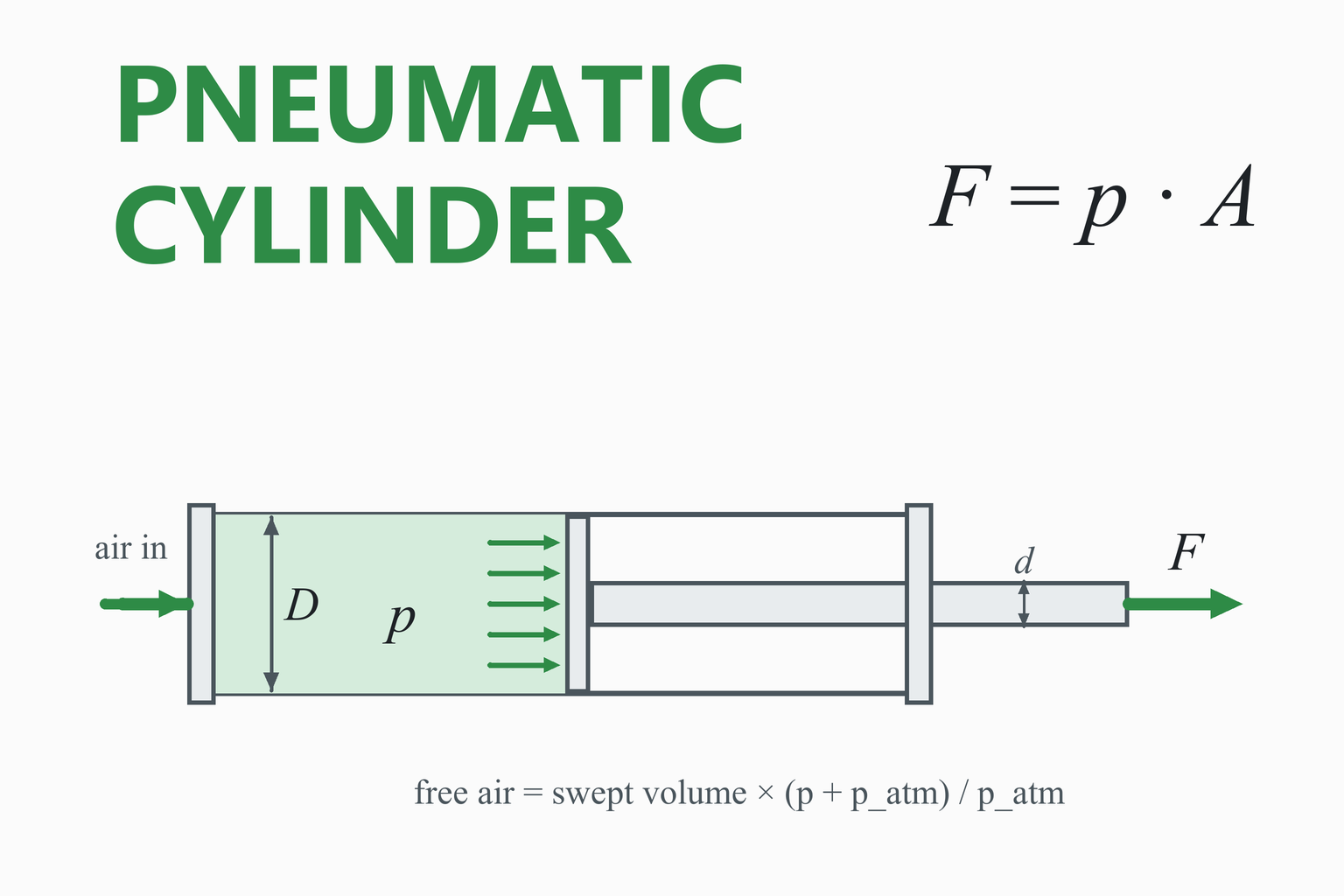
A pneumatic cylinder turns air pressure into a straight-line force. The force is simply the gauge pressure times the piston area, but two things catch people out: on the return stroke the piston rod takes up part of that area, so the pull force is lower than the push force, and every stroke uses a volume of compressed air that the compressor has to make up, which sets the size of the air supply. This calculator gives the push and pull force of a cylinder, the usable force after friction, the free-air consumption for the stroke and the cycle rate you enter, and it can work backwards from a load to the smallest standard bore that will move it.
Pneumatic Cylinder Calculator
Double-acting cylinder · gauge pressure · free air at the atmospheric pressure you set · losses entered as an efficiency
Usable force against pressure
—
Educational and preliminary-sizing tool. The results are steady-state estimates. They do not include acceleration, cushioning, valve and tubing restrictions, leakage, temperature or side loads, and the efficiency is your assumption, not a measured value for your cylinder.
Always size from the manufacturer’s data for the cylinder you will buy, and have safety-critical applications checked by a qualified engineer. Compressed air at these pressures can cause serious injury.
How to Use the Calculator
- Pick a mode. “Check a cylinder” gives forces and air use for a cylinder you have. “Find the bore for a load” works the other way round.
- Enter the cylinder. Choose a standard size or type the bore and rod diameter. Add the stroke and the number of full cycles per minute if you want the air consumption.
- Set the pressure at the cylinder, not at the compressor. Pressure drops along pipes and through valves, especially while the piston is moving.
- Choose an efficiency. It stands for seal friction and similar losses. Manufacturers’ catalogues quote theoretical force only, so some allowance is wise. The default of 90% is an assumption, not a rule.
- Add the load to see the margin and the pressure it needs, or read the push and pull forces and the free-air figures directly.
Tip: the compressor is sized from the free-air figure, not the volume inside the cylinder. A cylinder that holds 0.3 litres at 6 bar gauge uses about 2 litres of free air per stroke.
Worked Example: A 63 mm Cylinder at 6 bar
Problem. A double-acting cylinder has a 63 mm bore, a 20 mm rod and a 100 mm stroke. It runs at 6 bar gauge and makes 30 full cycles per minute. Find its push and pull force, the usable force at 90% efficiency and its air consumption.
- Areas.
Apiston = π × 63² / 4 = 3,117.2 mm² Arod = π × 20² / 4 = 314.2 mm² Aannulus = 2,803.1 mm²
- Theoretical force. 6 bar is 0.6 N/mm².
Fpush = 0.6 × 3,117.2 = 1,870.3 N Fpull = 0.6 × 2,803.1 = 1,681.9 N
- Usable force at 90%.
push 1,683.3 N pull 1,513.7 N
- Compression ratio with 101.325 kPa atmosphere.
(6 + 1.01325) / 1.01325 = 6.922
- Free air per stroke.
extend: 31.172 cm² × 10 cm × 6.922 = 2,158 cm³ = 2.158 Lretract: 28.031 cm² × 10 cm × 6.922 = 1,940 cm³ = 1.940 L
- Per cycle and per minute.
2.158 + 1.940 = 4.098 L per cycle × 30 = 122.9 L/min free air (7.4 m³/h, 4.3 ft³/min)
Result: the cylinder pushes with about 1,870 N and pulls with about 1,682 N in theory, which matches the catalogue values for a 63 mm cylinder with a 20 mm rod at 6 bar. After 90% efficiency it delivers about 1,683 N and 1,514 N, and it consumes roughly 123 litres per minute of free air at 30 cycles per minute. A compressor and air line sized for this one cylinder must supply at least that, plus the other users and the leakage.
Finding the bore for a load
To push 1,000 N at 6 bar with 90% efficiency, the exact bore is √(4 × 1,000 / (π × 0.9 × 600,000)) = 48.6 mm. The next standard bore is 50 mm, with a 20 mm rod, which gives a usable push force of 1,060 N and a pull force of 891 N. Switch the calculator to “Find the bore for a load” and enter 1,000 N to see the three nearest sizes.
How Pneumatic Cylinder Force Works
Compressed air pushes on the piston with the same pressure everywhere inside the chamber, so the force is that pressure times the area it acts on. Pressure is always the gauge pressure here, the pressure above the atmosphere on the other side of the piston, because the atmosphere pushes on both sides.
Push (extend) and pull (retract) force
D is the bore, d the rod diameter and p the gauge pressure. In SI units, pressure in pascals times area in square metres gives newtons. In practice, 1 bar on 1 cm² is 10 N.
Why the pull force is lower
On the extend stroke air acts on the whole piston. On the retract stroke it enters the rod side, where the rod takes up part of the area, so the effective area is the annulus. A rod that is 30% of the bore diameter removes 9% of the area, and a rod at 50% of the bore removes 25%. The air that is pushed out of the other side on retraction also has to leave through the valve, so a retract stroke is usually faster for the same flow.
Friction and efficiency
The seals drag against the bore, and the rod bearing and any side load add more friction. Catalogue force values are theoretical, so real cylinders deliver less. How much less depends on the seals, lubrication, speed and mounting: one sizing guide describes the loss as roughly 1 to 10 psi of the theoretical output depending on the seal type, and some calculator sites quote 10 to 20% of the force. The efficiency input lets you choose, and the 90% default is only a starting point. Friction is also a larger share of the output at low pressure and on the smaller retract area.
Air Consumption and Free Air
A cylinder does not use the air that is in it once; every stroke fills the chamber with air at working pressure, and that air is then exhausted. To know what the compressor has to supply, the volume is expressed as free air: the volume that the same mass of air would occupy at atmospheric pressure. That is the swept volume multiplied by the compression ratio.
Free air per stroke
A is the effective area (the full piston for the extend stroke, the annulus for the retract stroke), s the stroke, p the gauge pressure and patm the atmospheric pressure. The factor (p + patm) / patm is the compression ratio: 6.92 at 6 bar gauge at sea level. For a double-acting cylinder the volumes of the two strokes are added, and multiplying by the cycles per minute gives the flow the supply must deliver.
- Both strokes count. A common mistake is to use the full bore for both. The retract stroke uses the annulus, so the total is slightly less than twice the extend volume.
- The result is a flow of free air. It is quoted in litres per minute, cubic metres per hour or cubic feet per minute, depending on the supplier. Compressor ratings are quoted the same way.
- Add the dead volume. The tubing and fittings between valve and cylinder fill and empty on every stroke as well, and this calculator does not include them. A long, wide tube can add noticeably to the figure for a small cylinder.
- Altitude matters little for free air but it does change the gauge pressure you need for a given absolute pressure; set the atmospheric pressure if you work high above sea level.
Standard Cylinder Sizes
Round-bore cylinders for industry follow two common standards: ISO 6432 for small cylinders (bores from 8 to 25 mm) and ISO 15552 for the larger tie-rod type (bores of 32, 40, 50, 63, 80, 100, 125, 160, 200, 250 and 320 mm, with a rated pressure of 10 bar). The table lists the theoretical force and free-air use at 6 bar for the ISO 15552 bores, computed with the formulas on this page.
| Bore, mm | Rod, mm | Piston area, cm² | Push force, N | Pull force, N | Free air per cycle, L |
|---|---|---|---|---|---|
| 32 | 12 | 8.0 | 483 | 415 | 1,035.05 |
| 40 | 16 | 12.6 | 754 | 633 | 1,600.41 |
| 50 | 20 | 19.6 | 1,178 | 990 | 2,500.64 |
| 63 | 20 | 31.2 | 1,870 | 1,682 | 4,097.78 |
| 80 | 25 | 50.3 | 3,016 | 2,721 | 6,618.53 |
| 100 | 25 | 78.5 | 4,712 | 4,418 | 10,532.57 |
| 125 | 32 | 122.7 | 7,363 | 6,881 | 16,431.35 |
| 160 | 40 | 201.1 | 12,064 | 11,310 | 26,963.38 |
| 200 | 40 | 314.2 | 18,850 | 18,096 | 42,619.53 |
| 250 | 50 | 490.9 | 29,452 | 28,274 | 66,593.02 |
| 320 | 63 | 804.2 | 48,255 | 46,385 | 109,175.04 |
Choosing a size
- Start from the force you need at the pressure you will really have, then add margin for friction, acceleration and a sagging supply. One guide notes that a 100 psi system may fall to 80 psi or lower at peak demand.
- Check the pull force if the load is carried on the return stroke, or if the cylinder lifts a load that hangs on the rod.
- Think about speed. The piston speed is set by how fast air can flow in and out, so small valves and tubes slow a large cylinder however much force it has.
- Mind buckling and side loads. A long, slender rod loaded in compression can buckle, and a cylinder is meant to push or pull along its axis. Use the manufacturer’s tables for long strokes.
Common Mistakes
Using the push force for the pull stroke
The rod removes part of the area on the retract side, so the pull force is always lower. Check the direction that carries the load.
Using the compressor pressure
The pressure that matters is the one at the cylinder while it moves. Regulators, long lines and small valves can lose a bar or more.
Sizing with no margin
A cylinder that just matches the load has no force left to accelerate it. Friction and pressure sag eat the rest.
Mixing free air with working-pressure volume
Compressors are rated in free air. The volume inside the cylinder at 6 bar is about one seventh of the free-air figure.
Mixing units
1 bar is 14.5 psi, and 1 lbf is 4.448 N. Use the unit drop-downs rather than converting by hand.
Ignoring a vertical load
A load that hangs from the cylinder adds its weight to the force on one stroke and takes it from the other.
Assumptions and Limitations
- Double-acting, single-rod cylinders. Single-acting spring-return cylinders, through-rod cylinders, rodless cylinders and rotary actuators are not covered.
- Steady-state force. The force is the static value at the pressure you enter. Real force during a stroke depends on how fast the pressure builds, the load acceleration and the exhaust back-pressure.
- Efficiency is an input. It is a single number for all losses. Use the manufacturer’s data if you have it.
- Free air at one atmosphere. Air temperature and humidity are not included. The compression ratio is based on the atmospheric pressure you enter.
- No dead volume or leakage. Tubing, fittings, cushions and leaks add to the real consumption.
- Standard rod diameters are common pairings, not a substitute for your cylinder’s data sheet; type your own rod size if it differs.
How This Calculator Was Verified
The force, air-consumption and sizing equations were compared with an independent Python implementation that works in different units (areas in cm², air as a number of moles from the ideal-gas law rather than a volume ratio) over thousands of random cylinders; the two agree to rounding error. The results were also compared with manufacturer catalogue values for the 32 mm and 63 mm ISO 15552 cylinders at 6 bar (483 N and 415 N for the 32 mm bore with a 12 mm rod; 1,870 N and 1,682 N for the 63 mm bore with a 20 mm rod), and the free-air formula with the form used by cylinder-sizing calculators, which multiplies the swept volume by the compression ratio and counts both strokes. The page also checks itself live:
| Check | Expected | Calculator |
|---|---|---|
| Areas, 63 mm bore with 20 mm rod | 3,117.2 mm² piston, 2,803.1 mm² annulus | … |
| Forces at 6 bar, 63 mm bore with 20 mm rod (catalogue 1,870 N and 1,682 N) | push 1,870.3 N, pull 1,681.9 N | … |
| Forces at 6 bar, 32 mm bore with 12 mm rod (catalogue 483 N and 415 N) | push 482.5 N, pull 414.7 N | … |
| Compression ratio at sea level | 6.922 at 6 bar gauge; 1.000 at zero gauge | … |
| Free air, 63 mm bore, 20 mm rod, 100 mm stroke, 6 bar, 30 cycles per minute | 2.158 L, 1.940 L, 4.098 L per cycle; 122.9 L/min | … |
| Unit conversions | 6 bar = 87.02 psi; 1 lbf = 4.4482 N; 1 L/min = 0.03531 ft³/min | … |
| Bore for 1,000 N push at 6 bar and 90% efficiency | 48.6 mm, next standard bore 50 mm | … |
The “Calculator” column is computed live, by the same code that runs the calculator, in your browser. The standard rod diameters other than those for the 32 mm and 63 mm bores are commonly published pairings that I could not check against the standards themselves.
Frequently Asked Questions
How do I calculate the force of a pneumatic cylinder?
Multiply the gauge pressure by the piston area: F = p × π D² / 4. At 6 bar a 63 mm bore gives 0.6 N/mm² × 3,117 mm² = 1,870 N. For the retract stroke use the annulus area, the piston area minus the rod area. Real cylinders deliver less because of seal friction, so the calculator also shows a usable force at the efficiency you enter.
Why is the pull force of a cylinder lower than the push force?
On the retract stroke the air works on the rod side of the piston, where the piston rod takes up part of the area. The effective area is the annulus, so for the same pressure the force is lower. A rod that is half the bore diameter removes a quarter of the area.
How much air does a pneumatic cylinder use?
Each stroke fills the chamber with air at working pressure, and the compressor has to supply it as free air: the swept volume multiplied by the compression ratio (p + patm) / patm. For a double-acting cylinder add the extend stroke (full piston area) and the retract stroke (annulus area), then multiply by the number of cycles per minute. A 63 mm cylinder with a 100 mm stroke at 6 bar uses about 4.1 litres of free air per cycle, or about 123 litres per minute at 30 cycles per minute.
What is free air, and what is the compression ratio?
Free air is air measured at atmospheric pressure, the way compressor output is rated. The compression ratio is the absolute working pressure divided by atmospheric pressure, which is 6.92 for 6 bar gauge at sea level. A litre of cylinder volume at 6 bar gauge therefore corresponds to about 6.9 litres of free air.
What efficiency should I use for a pneumatic cylinder?
There is no single value. Friction depends on the seals, lubrication, speed, mounting and side load, and manufacturers publish theoretical force. One sizing guide gives the friction loss as roughly 1 to 10 psi of the theoretical output, and some calculators use 10 to 20% of the force. The default of 90% here is only a starting point; use the cylinder maker’s data if you have it, and keep a margin over the load.
How do I choose the bore for a load?
Divide the force you need by the pressure you will really have at the cylinder and by the efficiency to get the piston area, then round the bore up to the next standard size. If the load is carried on the pull stroke, use the annulus area, which depends on the rod diameter. The “Find the bore for a load” mode does this with the standard bores and rods and shows the nearest sizes.
What are ISO 15552 and ISO 6432 cylinders?
They are standards for the dimensions of round pneumatic cylinders so that parts from different makers interchange. ISO 15552 covers the larger tie-rod cylinders with bores of 32, 40, 50, 63, 80, 100, 125, 160, 200, 250 and 320 mm at a rated pressure of 10 bar, and ISO 6432 covers the small cylinders with bores of 8 to 25 mm.
Does the stroke change the force?
No. The force depends only on the pressure and the piston area. The stroke changes the air consumption, which is proportional to it, and the time a stroke takes. A long stroke also makes a slender rod more likely to buckle when it pushes, so check the manufacturer’s limits for long strokes.
Can I use the calculator for a single-acting cylinder?
Partly. For the powered stroke the force is the same pressure times area, but the return spring subtracts from the usable force, and the air consumption is only that of the powered stroke. Take the spring force from the data sheet and subtract it from the force shown here.
What compressor size do I need?
Add up the free-air consumption of every consumer on the line, including all cylinders at their duty cycle, and allow for leakage and future additions; compressor ratings are given in free air, so the figures are comparable. This calculator gives the figure for one cylinder, and it does not include the dead volume of tubing and fittings.
References and Further Reading
- ISO 15552, Pneumatic fluid power: cylinders with detachable mountings, 1,000 kPa (10 bar) series, bores from 32 to 320 mm. (Basic, mounting and accessory dimensions.)
- ISO 6432, Pneumatic fluid power: single rod cylinders, 1,000 kPa (10 bar) series, bores from 8 to 25 mm.
- ISO 8778, Pneumatic fluid power: standard reference atmosphere.
- Esposito, A. Fluid Power with Applications. Pearson. (Cylinder force, speed and air-consumption relations.)
- Manufacturers’ cylinder catalogues (for example Festo, SMC, Parker, Bosch Rexroth): theoretical force tables at 6 bar and the cylinder data you should size from.
- Fluid power trade guides on matching a pneumatic cylinder to a load (friction allowance, pressure margin and supply sag).