
Bernoulli Equation and Flow Rate Calculator
Flow rate and velocity in a pipe, the pressure change between two points, flow from a Venturi, orifice or Pitot tube, and the discharge of a tank
Two ideas explain most of what a fluid does in a pipe. Continuity says that what flows in must flow out, so a fluid speeds up where the pipe narrows. Bernoulli’s equation says that, along the flow, pressure, speed and height trade off against one another, so the pressure falls where the speed rises. This calculator puts both to work in four ways: the flow rate, velocity or diameter of a pipe from the other two; the pressure at a second point when you know the flow, the pipe sizes, the heights and any head loss; the flow through a Venturi meter or orifice plate (or the velocity from a Pitot tube) from a measured pressure difference; and the speed, flow and draining time of a tank with an outlet. Everything is shown in metric and customary units.
Bernoulli and Flow Rate Calculator
Steady flow of an incompressible fluid · Bernoulli’s equation along a streamline, with an optional head loss
Sketch of your case
—
Educational and preliminary-design tool. Bernoulli’s equation is an idealisation: steady flow of a fluid with constant density, along a streamline, without friction unless you enter a head loss. It works well for short, smooth, converging flows and for first estimates, and badly for long pipes, sudden changes, pumps and turbines, or gas flow close to the speed of sound.
Discharge coefficients are typical values; use the one for your actual meter or outlet. Check any design that matters with the applicable standard and a qualified engineer.
How to Use the Calculator
- Choose the calculation and the fluid. Water and air at 20 °C are built in; pick “other fluid” and type the density for anything else. Set the units you want to work in: the fields convert when you change them.
- Continuity. Enter two of diameter, velocity and flow rate to get the third. Add a second diameter to see how fast the fluid moves where the pipe changes size.
- Pressure between two points. Enter the pressure at point 1, the flow (or the velocity), the pipe diameters and the heights of both points. If friction matters, add the head lost between them. The result is the pressure at point 2, with the head at each point so you can see where the energy goes.
- Venturi, orifice or Pitot tube. Enter the pipe and throat diameters, the coefficient and the pressure difference you measured to get the flow, or the flow to get the pressure difference you should see.
- Tank discharge. Enter the liquid height above the outlet, the outlet diameter and the coefficient. Add the tank diameter and a final height to get the time it takes to drain.
Tip: pressure in the equation can be gauge or absolute as long as you use the same kind at both points. Choose “absolute” if you want the calculator to check that the result is physically possible at point 2.
Worked Examples
1. Flow and velocity in a pipe that narrows
Problem. Water flows at 2.5 m/s in a 50 mm pipe that narrows to 25 mm. What is the flow rate, the mass flow and the velocity in the narrow section?
- Flow rate
A1 = π × 0.05² / 4 = 1.9635 × 10⁻³ m² Q = A1 v1 = 1.9635 × 10−3 × 2.5 = 4.909 × 10⁻³ m³/s = 4.909 L/s = 294.5 L/min
- Mass flow of water (998.2 kg/m³): 998.2 × 4.909 × 10−3 = 4.90 kg/s.
- Velocity in the narrow section
v2 = Q / A2 = v1 (D1 / D2)² = 2.5 × (50 / 25)² = 10 m/s
Halving the diameter quarters the area, so the velocity is four times higher.
2. Pressure at a second point
Problem. Water flows at 10 L/s from a 100 mm pipe at 200 kPa gauge into a 50 mm pipe whose measuring point is 2 m higher. The head lost to friction between the points is 0.5 m. What is the pressure at point 2?
- Velocities
v1 = 0.010 / (π × 0.1² / 4) = 1.273 m/s v2 = 0.010 / (π × 0.05² / 4) = 5.093 m/s
- Bernoulli with a head loss
p2 = p1 + ½ρ(v1² − v2²) + ρg(z1 − z2 − hL)= 200,000 + ½ × 998.2 × (1.621 − 25.938) + 998.2 × 9.80665 × (0 − 2 − 0.5)= 200,000 − 12,137 − 24,473 = 163,391 Pa = 163.4 kPa
Result: p2 = 163.4 kPa gauge. The narrowing alone would have cost 12.1 kPa (the pressure turned into speed), and the extra height with the friction loss costs another 24.5 kPa. The total head is 20.51 m at point 1 and 20.01 m at point 2, the difference being the 0.5 m lost.
3. A Venturi meter
A Venturi meter in a 100 mm water pipe has a 50 mm throat and a discharge coefficient of 0.98. A pressure difference of 20 kPa is measured between the inlet and the throat. The diameter ratio is β = 0.5, so E = 1 / √(1 − 0.54) = 1.0328, and Q = C E Athroat √(2Δp / ρ) = 0.98 × 1.0328 × 1.9635 × 10−3 × √(2 × 20,000 / 998.2) = 12.58 L/s. The throat velocity is 6.41 m/s and the pipe velocity 1.60 m/s. Without the coefficient the ideal flow would be 12.84 L/s, 2% more.
4. Draining a tank
A tank has a 25 mm outlet 2 m below the water surface, with a discharge coefficient of 0.62. The jet speed is √(2 × 9.80665 × 2) = 6.26 m/s and the flow is 0.62 × 4.909 × 10−4 × 6.263 = 1.906 L/s. If the tank is 1 m in diameter, the time for the level to fall from 2 m to 0.5 m is (Atank / C a) × √(2/g) × (√2 − √0.5) = 2,580.6 × 0.4516 × 0.7071 = 824 s, about 13.7 minutes.
5. A Pitot tube in a duct
A Pitot tube in an air duct reads a difference of 500 Pa between the stagnation and the static pressure. With air at 1.204 kg/m³ the velocity at the tip is v = √(2 × 500 / 1.204) = 28.8 m/s.
The Equations
Continuity and Bernoulli
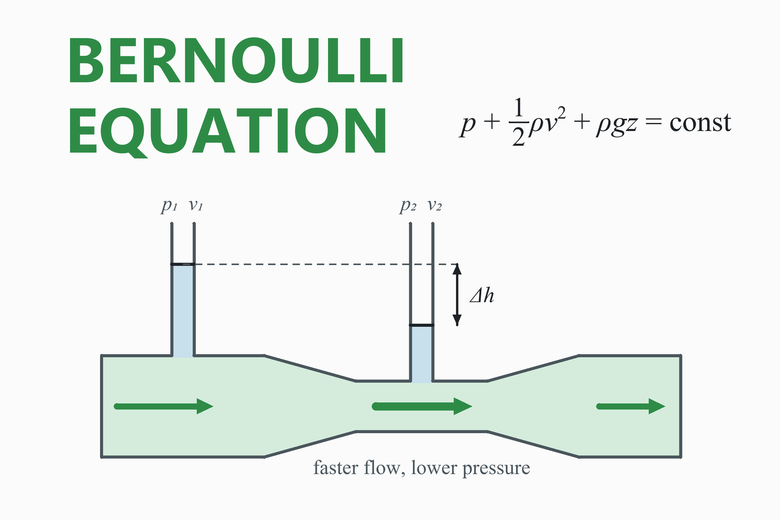
For a steady flow of a fluid of constant density, the volume flow rate Q is the same at every cross-section, so A1v1 = A2v2. Along a streamline, the sum of the pressure p, the kinetic energy per unit volume ½ρv² and the potential energy per unit volume ρgz stays constant. It is the conservation of energy, written per unit volume of fluid.
The head form
Divide by ρg and every term becomes a height, called a head: p/ρg + v²/2g + z = H. The three terms are the pressure head, the velocity head and the elevation head, and H is the total head. A real flow loses some of the total head to friction between the two points, so p1/ρg + v1²/2g + z1 = p2/ρg + v2²/2g + z2 + hL, which is the form the calculator uses. For water, 1 m of head is about 9.79 kPa.
Assumptions
- Steady flow: the velocity and pressure at a point do not change with time.
- Incompressible: the density is constant. That is true for liquids and, as a common rule, for gases up to about Mach 0.3 (a speed of roughly 100 m/s in air), where the density changes by only a few percent.
- Along a streamline, and with a uniform velocity across each section, so that one velocity describes the section.
- No friction and no work: unless you add a head loss, and with no pump or turbine between the two points. With a pump, add the head it delivers; with a turbine, subtract the head it takes.
The Venturi effect and the flow meters
Where the pipe narrows, continuity makes the fluid faster and Bernoulli makes the pressure lower. Measure the pressure drop between the wide and the narrow section and the flow follows: Q = C E Ad √(2Δp / ρ), where Ad is the area of the throat, E = 1 / √(1 − β4) allows for the speed the fluid already has upstream (β = d / D) and C is the discharge coefficient that corrects for friction and the real flow pattern. A Venturi meter has a smooth, gradual throat and recovers most of the pressure, with coefficients of about 0.95 to 0.99; an orifice plate is a plate with a hole, cheap and simple but with a lower coefficient (about 0.6 for a sharp edge) and a permanent pressure loss. Standards such as ISO 5167 give the coefficients and limits for accurate metering.
The Pitot tube
A tube facing the flow brings the fluid at its tip to rest and so reads the stagnation pressure p + ½ρv²; a wall tap or side holes read the static pressure p. The difference is ½ρv², so v = √(2Δp / ρ). It gives the velocity at the tip, not the average over the pipe, which is lower because the fluid slows near the wall.
Torricelli’s law
Apply Bernoulli’s equation from the surface of a large tank, where the liquid is almost at rest, to the jet leaving the outlet at atmospheric pressure: ½v² = gh, so v = √(2gh), the speed an object reaches after falling through the height h. If the tank is pressurised, replace h by h + pt / ρg. The real flow is the area of the outlet times this speed times a coefficient C, because the jet narrows just outside a sharp-edged hole (the vena contracta). As the level falls, so does the flow, which gives the draining time T = (Atank / C a) √(2/g) (√h1 − √h2).
Cavitation and the vacuum limit
Bernoulli’s equation can predict a pressure below zero absolute, which is impossible. Long before that, a liquid vaporises when the pressure falls to its vapour pressure (about 2.3 kPa absolute for water at 20 °C), forming bubbles that collapse violently: this is cavitation, and it limits how much a pipe can be narrowed or how high a liquid can be sucked. The calculator warns when point 2 reaches these limits.
Friction
In a long pipe the head lost to friction is large and cannot be neglected. Work it out with the pipe pressure drop calculator (the Reynolds number tells you whether the flow is laminar or turbulent), convert the pressure drop to a head by dividing by ρg, and enter it as the head loss.
Common Mistakes
Using the radius instead of the diameter
The area is πD²/4. Putting a radius into the diameter field makes the area four times too small.
Mixing gauge and absolute pressure
Use the same kind at both points. The difference between the two is the same, but a cavitation check needs absolute pressure.
Mixing units
Millimetres with metres, or litres with cubic metres, gives errors of factors of a thousand. The calculator converts for you when you change a unit.
Ignoring friction in a long pipe
Bernoulli without a loss over metres of pipe overestimates the pressure downstream. Add the head loss.
Using it for fast gas
The incompressible form is not valid for gas flow above about Mach 0.3, or for large pressure changes in a gas.
Forgetting the discharge coefficient
The ideal flow of a meter or an outlet is higher than the real one, by about 2% for a good Venturi and by more than 60% for a sharp-edged hole.
Assumptions and Limitations
- Steady, incompressible, one-dimensional flow along a streamline, with the velocity taken as the flow rate divided by the area.
- No pumps or turbines between the two points; the head loss is your input.
- Pitot tube results are local velocities at the tip, not average velocities; the “flow if this were the average speed” line is only an upper estimate.
- Venturi and orifice results use the coefficient you enter, which varies with the meter, the diameter ratio and the Reynolds number; for accurate metering follow the standard.
- Tank draining assumes the outlet is small compared with the tank, a constant coefficient, and a constant gauge pressure above the liquid.
How This Calculator Was Verified
The results were compared with an independent Python implementation over 3,000 random cases. Continuity was checked against the familiar pipe-flow rule gallons per minute = 2.448 d² v (d in inches, v in ft/s), which uses different constants. The pressure at the second point was rebuilt in US customary units and from the heads, and the total heads at the two points were checked to differ by exactly the head loss. For the meters, the flow found from a pressure difference was put back into Bernoulli’s equation and continuity to recover the pressure difference, which checks the velocity-of-approach factor. The draining time was compared with a numerical integration of the falling level. The page also checks itself live:
| Check | Expected | Calculator |
|---|---|---|
| 50 mm pipe at 2.5 m/s, narrowing to 25 mm, water | 4.909 L/s = 294.5 L/min; 10.000 m/s; 4.900 kg/s | … |
| Water, 10 L/s, 100 mm to 50 mm, 200 kPa, 2 m up, 0.5 m loss | 1.273 and 5.093 m/s; 163.39 kPa; heads differ by 0.5000 m | … |
| Venturi 100/50 mm, C 0.98, 20 kPa, water | 12.580 L/s; β 0.50; the same 20 kPa from that flow | … |
| Tank, h 2 m, 25 mm outlet, C 0.62, 1 m tank down to 0.5 m | 6.263 m/s; 1.906 L/s; 824.1 s | … |
| Pitot tube in air, 500 Pa | 28.820 m/s | … |
| Same pipe, point 2 raised 10 m, water, 100 kPa gauge | p2 = 100 − 97.89 = 2.110 kPa (hydrostatic) | … |
| Total heads with a 0.3 m loss, 80 mm to 30 mm pipe | H1 − H2 = 0.3000 m | … |
The “Calculator” column is computed live, by the same code that runs the calculator, in your browser. The densities of water and air are the values at 20 °C and standard atmospheric pressure (101.325 kPa).
Frequently Asked Questions
What is Bernoulli’s equation?
Bernoulli’s equation states that along a streamline in a steady, frictionless flow of a fluid of constant density, the sum of the pressure, the kinetic energy per unit volume and the potential energy per unit volume is constant: p + ½ρv² + ρgz = constant. It is a statement of the conservation of energy, and it explains why the pressure falls where a fluid speeds up and rises where it slows down.
What is the Bernoulli equation in head form?
Dividing by ρg gives p/ρg + v²/2g + z = H, where the three terms are the pressure head, the velocity head and the elevation head, each a height of fluid, and H is the total head. Between two points in a real flow, p1/ρg + v1²/2g + z1 = p2/ρg + v2²/2g + z2 + hL, where hL is the head lost to friction between them.
What are the assumptions of Bernoulli’s equation?
Steady flow, a fluid of constant density, flow along a streamline with a uniform velocity over each cross-section, no friction (or a head loss that you add), and no pump or turbine between the two points. For gases the constant-density assumption holds as a rule up to about Mach 0.3.
How do I calculate flow rate from pipe diameter and velocity?
Multiply the cross-sectional area by the velocity: Q = A v, with A = πD²/4. A 50 mm pipe at 2.5 m/s carries 1.9635 × 10−3 m² × 2.5 m/s = 4.909 L/s. This is the continuity equation: for an incompressible fluid the flow rate is the same at every section, so A1v1 = A2v2, and to size a pipe for a flow and a chosen velocity, D = √(4Q / πv).
Why does the pressure drop where a pipe narrows?
Continuity makes the fluid move faster in the narrow section. Faster fluid has more kinetic energy per unit volume, and by Bernoulli’s equation that energy must come from the pressure, so the pressure is lower. This is the Venturi effect. Part of the pressure comes back when the pipe widens again, less the losses.
How do I calculate flow from a Venturi meter or orifice plate?
Q = C E Ad √(2Δp / ρ), where Δp is the pressure difference between the inlet and the throat (or across the plate), Ad the area of the throat or hole, E = 1 / √(1 − β4) the velocity-of-approach factor with β = d / D, and C the discharge coefficient: about 0.95 to 0.99 for a Venturi meter and about 0.6 for a sharp-edged orifice plate. For accurate metering follow the standard that applies, ISO 5167.
How do I find the speed of water leaving a tank?
Use Torricelli’s law: v = √(2gh), where h is the height of the liquid surface above the outlet. For h = 2 m this is 6.26 m/s. The flow is Q = C a √(2gh), with a the outlet area and C a coefficient of about 0.6 for a sharp-edged hole, because the jet narrows after leaving it. For a pressurised tank, use h + p / ρg in place of h.
How do I include friction losses?
Work out the pressure drop due to friction between the two points, for example with the pipe pressure drop calculator, divide it by ρg to turn it into a head, and enter it as the head loss hL. The calculator then subtracts it from the total head, so the pressure at the second point is lower by ρg hL than in the ideal flow.
Can I use Bernoulli’s equation for gases?
Yes, as long as the density hardly changes: for flow below about Mach 0.3 (roughly 100 m/s in air at room temperature) and for small pressure changes. For faster flows or large pressure drops the compressible form of the equations is needed, because the density of the gas changes along the flow.
What does a Pitot tube measure?
It measures the velocity of the fluid at the tip of the tube, from the difference between the stagnation pressure at the tip and the static pressure: v = √(2Δp / ρ). It is not the average velocity in the pipe, which is lower than the centreline velocity because the fluid is slowed by the wall, so for flow measurement the tube is traversed across the pipe or the reading is corrected.
References and Further Reading
- White, F. M. Fluid Mechanics. McGraw-Hill. (Continuity, the Bernoulli equation, flow measurement and the discharge coefficient.)
- Çengel, Y. A., & Cimbala, J. M. Fluid Mechanics: Fundamentals and Applications. McGraw-Hill. (Bernoulli’s equation, the energy equation with head loss, and Pitot and Venturi measurements.)
- Munson, B. R., Young, D. F., & Okiishi, T. H. Fundamentals of Fluid Mechanics. Wiley. (Bernoulli’s equation and its restrictions, flow rate measurement.)
- ISO 5167. Measurement of fluid flow by means of pressure differential devices inserted in circular cross-section conduits running full. (Orifice plates, nozzles and Venturi tubes.)