
Calculate the Fatigue Safety Factor of a Shaft: Goodman, Soderberg, Gerber and ASME
Endurance limit with Marin factors, von Mises stresses, four failure criteria, a Goodman diagram and a minimum-diameter mode
A shaft that carries a steady load can still fail by fatigue, because a rotating shaft turns the bending stress from tension to compression every revolution. The standard way to check it is a Goodman diagram: plot the alternating and mean stress and compare them with a failure line. This calculator does the whole job for steel shafts. It corrects the endurance limit with the Marin factors (surface, size, temperature, reliability), combines bending and torsion into von Mises alternating and mean stresses with your stress concentration factors, and returns the factor of safety by the DE-Goodman, DE-Soderberg, DE-Gerber and DE-ASME elliptic criteria, plus a first-cycle yield check. Or give it a target factor of safety and it finds the smallest diameter.
Shaft Fatigue Safety Factor Calculator
Steel shaft · round solid section · infinite life · bending and torsion at the critical point
| Shaft diameter used | — |
|---|---|
| Uncorrected endurance limit Se′0.5 Sut, capped at 700 MPa | — |
| Surface factor ka | — |
| Size factor kb | — |
| Other factors | — |
| Reliability factor ke | — |
| Corrected endurance limit Se | — |
| Von Mises alternating stress σa′ | — |
| Von Mises mean stress σm′ | — |
| Factor of safety, DE-Goodman | — |
| Factor of safety, DE-Soderberg | — |
| Factor of safety, DE-Gerber | — |
| Factor of safety, DE-ASME elliptic | — |
| Lowest of the four | — |
| First-cycle yield check ny = Sy / σmax′Langer; all loads at their peak | — |
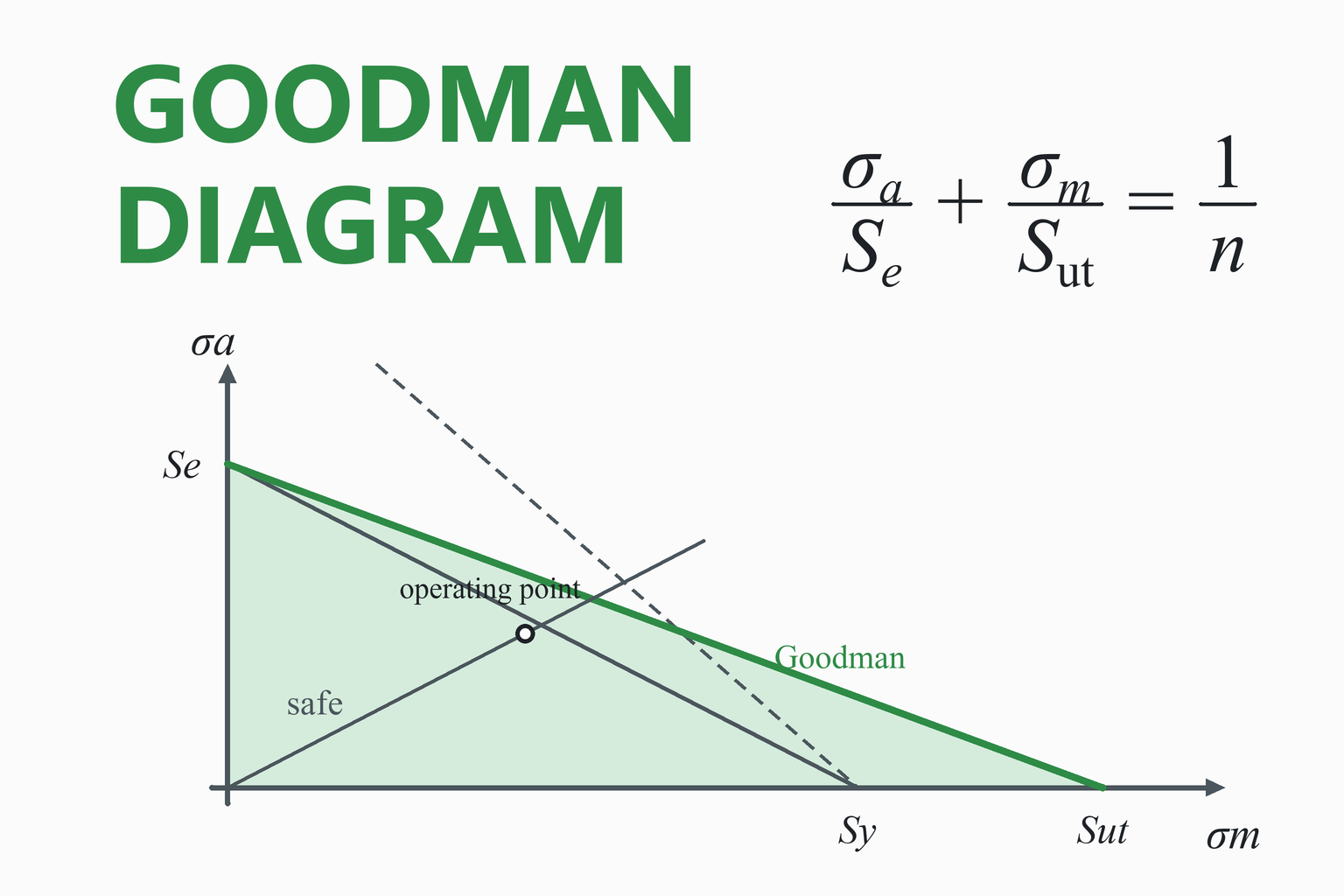
Goodman diagram: your operating point against the failure lines
—
Educational and preliminary-design tool. It estimates the infinite-life fatigue safety of a smooth or notched round steel shaft from standard textbook relations. It does not replace testing, the applicable code, or a full analysis that includes shaft deflection, critical speed, bearings, keys and fits, or variable-amplitude loading.
Fatigue results are sensitive to surface finish, stress concentration and the endurance limit. Have safety-critical shafts checked by a qualified engineer.
How to Use the Calculator
- Choose check or design mode. To check a shaft you already have, enter its diameter at the critical section. To size a new shaft, enter a target factor of safety instead and the calculator finds the smallest diameter.
- Enter the loads at the critical section. Take the bending moment and the torque at the point where the shaft is most likely to fail: usually a shoulder, keyway or groove near a bearing or gear. For a rotating shaft with a steady load, the bending moment is alternating and the transmitted torque is a mean load.
- Pick the material or enter Sut and Sy from your material certificate.
- Set the endurance limit. Let the calculator estimate it from the Marin factors, or enter a tested value for the actual part.
- Enter the fatigue stress concentration factors Kf and Kfs for the critical feature. Use 1 for a smooth section.
- Read the four factors of safety and the diagram. A factor above 1 means the operating point is inside the line; it is the factor by which all loads could grow before the line is reached.
Tip: Compare the four results. If Goodman and Soderberg disagree greatly, mean stress is large compared with the yield strength. If any factor is below about 1.5 the design is sensitive to the assumptions, and the stress concentration factor is usually the one that matters most.
Worked Example: A Steel Shaft with a Shoulder
Problem. A 30 mm diameter shaft of cold-drawn AISI 1045 steel (Sut = 630 MPa, Sy = 530 MPa) has a machined shoulder. At the shoulder it carries a rotating bending moment of 150 N·m and a steady torque of 120 N·m. Use Kf = 1.8 for bending and Kfs = 1.4 for torsion, and a reliability of 99%. Find the fatigue factor of safety and the diameter needed for n = 2.
- Endurance limit of the test bar.
Se′ = 0.5 Sut = 0.5 × 630 = 315 MPa
- Marin factors.
ka = 4.51 × 630−0.265 = 0.8172 (machined surface)kb = (30 / 7.62)−0.107 = 0.8636 (size)kc = 1, kd = 1, ke = 0.814 (combined loading, room temperature, 99%)
- Corrected endurance limit.
Se = 0.8172 × 0.8636 × 0.814 × 315 = 181.0 MPa
- Von Mises stresses (16 / πd³ = 188,630 m⁻³). The bending moment is alternating and the torque is a mean load.
σa′ = (16/πd³) √[4 (Kf Ma)²] = 188,630 × 540 = 101.9 MPaσm′ = (16/πd³) √[3 (Kfs Tm)²] = 188,630 × 291.0 = 54.9 MPa
- Goodman factor of safety.
1/n = σa′/Se + σm′/Sut = 101.9/181.0 + 54.9/630 = 0.5629 + 0.0871 = 0.6500n = 1.54
- The other criteria for the same stresses: Soderberg 1.50, Gerber 1.74 and ASME elliptic 1.75. The first-cycle yield check gives ny = 530 / 115.7 = 4.58, so yielding is not a concern.
- Diameter for n = 2. Because kb depends on d, the calculator solves for d by iteration: 32.8 mm for Goodman, and 33.1, 31.5 and 31.4 mm for Soderberg, Gerber and ASME. A standard 35 mm shaft would satisfy all four.
Result: the 30 mm shaft has a Goodman factor of safety of about 1.5 at 99% reliability (1.50 to 1.75 across the four criteria), and about 33 mm would be needed for n = 2. Notice that almost all of the damage comes from the alternating bending term (0.563 of the 0.650); the steady torque adds only 0.087. That is typical for a rotating shaft, and it is why reducing the stress concentration at the shoulder, for instance with a larger fillet radius, is often more effective than choosing a stronger steel.
What Is Fatigue and Why Do Shafts Suffer from It?
A part that is loaded and unloaded many times can crack and break at a stress far below its yield strength. This is fatigue. A crack starts at a tiny flaw or stress concentration, grows a little with every cycle and finally leaves too little material to carry the load. Steels show an endurance limit: a stress amplitude below which the part can run for an effectively unlimited number of cycles. That is the target of an infinite-life design, and it is what this calculator checks.
A rotating shaft is the classic case. Suppose it carries a gear with a steady force. The bending moment at a section does not change, but the shaft rotates inside it, so any point on the surface passes through the tension side and then the compression side once every revolution. The bending stress at that point therefore reverses completely between a positive and a negative value: it is an alternating stress with zero mean. A steady transmitted torque, on the other hand, gives a constant shear stress, a mean stress. Real shafts have both, and the Goodman diagram is how the two are combined.
The Endurance Limit and the Marin Factors
The endurance limit measured on a small, polished test bar is, for steels, about half the tensile strength: Se′ = 0.5 Sut up to a tensile strength of 1400 MPa, above which it is taken as 700 MPa. A real shaft is rougher, larger and less certain, so Marin’s equation reduces the test value:
Marin equation
Each factor is a number around or below 1 that captures one way the real part differs from the test bar.
| Factor | What it covers | Value |
|---|---|---|
| ka | Surface finish | ka = a Sutb: ground 1.58 and −0.085; machined or cold-drawn 4.51 and −0.265; hot-rolled 57.7 and −0.718; as-forged 272 and −0.995 (limited to 1) |
| kb | Size | (d / 7.62 mm)−0.107 for 2.79 ≤ d ≤ 51 mm; 1.51 d−0.157 (d in mm) for 51 < d ≤ 254 mm |
| kc | Load type | 1 here, because bending and torsion are combined with the von Mises stress. (For pure axial or pure torsional fatigue the textbook values are lower, 0.85 and 0.59.) |
| kd | Temperature | 1.0 at ordinary temperatures, lower in a hot shaft; enter your own value |
| ke | Reliability | ke = 1 − 0.08 z: 50% 1.000, 90% 0.897, 95% 0.868, 99% 0.814, 99.9% 0.753, 99.99% 0.702, 99.999% 0.659, 99.9999% 0.620 |
| Other | Corrosion, plating, residual stress and so on | 1.0 if none; use your own value |
The surface factor shows why a rough finish hurts: for the same steel, a hot-rolled surface can cost much more than a ground one, and the loss grows with the strength of the steel, since stronger steels are more notch sensitive. This is one reason high-strength steel is not a cure for fatigue problems.
Stress Concentration: Kt and Kf
Shoulders, keyways, grooves and holes concentrate stress. The theoretical factor Kt comes from the geometry (for example, a sharp shoulder fillet has a large value and a generous radius a smaller one). In fatigue the real effect is usually a little smaller, so the fatigue concentration factor is
Fatigue stress concentration factor
q is the notch sensitivity, between 0 (the material ignores the notch) and 1 (it feels the full Kt). Use Kfs and the torsional values for shear. If you do not know q, take q = 1.
The factors are applied to the stress amplitudes of the loads. This calculator applies Kf to both the alternating and the mean bending stress and Kfs to both torsional components, which is the conservative practice used in the textbook method.
Combining Bending and Torsion: Von Mises Stresses
For a solid round shaft of diameter d, the bending stress at the surface is σ = 32 Kf M / (πd³) and the torsional shear stress is τ = 16 Kfs T / (πd³). The distortion-energy (von Mises) equivalent stress for this plane stress state is √(σ² + 3τ²). Applying it separately to the alternating and the mean components gives
Equivalent alternating and mean stress
These are the building blocks of every criterion below. The prefix “DE” stands for distortion energy.
The Four Failure Criteria
| Criterion | Failure line | Factor of safety n | Character |
|---|---|---|---|
| DE-Goodman | σa/Se + σm/Sut = 1/n | 1 / (σa′/Se + σm′/Sut) | Straight line to the tensile strength. Conservative; widely used. |
| DE-Soderberg | σa/Se + σm/Sy = 1/n | 1 / (σa′/Se + σm′/Sy) | Straight line to the yield strength. Most conservative; also guards against yielding. |
| DE-Gerber | nσa/Se + (nσm/Sut)² = 1 | ½ (Sut/σm′)² (σa′/Se) [ −1 + √(1 + (2σm′Se / (Sutσa′))²) ] | Parabola that follows test data for ductile steel closely. Needs a separate yield check. |
| DE-ASME elliptic | (nσa/Se)² + (nσm/Sy)² = 1 | 1 / √[ (σa′/Se)² + (σm′/Sy)² ] | Ellipse through Se and Sy. Between Gerber and Soderberg; includes yielding approximately. |
The criteria agree when the mean stress is small, because they all pass through the endurance limit on the vertical axis. They differ when the mean stress is large. For a shaft with fully reversed bending and a modest steady torque, the choice changes the answer by 10 to 20%, which is well inside the uncertainty of the endurance limit itself.
Sizing a shaft directly
When the endurance limit does not depend on the diameter, each criterion can be solved for d. With A = √[4(KfMa)² + 3(KfsTa)²] and B = √[4(KfMm)² + 3(KfsTm)²], the DE-Goodman result is
DE-Goodman diameter
For Soderberg replace Sut by Sy. The size factor kb inside Se depends on d, so in practice you iterate: guess d, find kb, find d again, repeat. The calculator’s design mode does this for all four criteria.
Do Not Forget Yielding
The Goodman and Gerber lines protect against fatigue but do not strictly prevent yielding in the first cycle. The calculator therefore also checks the peak stress, with the alternating and mean parts of every load added: ny = Sy / σmax′, where σmax′ = √[ (32 Kf(Ma+Mm)/πd³)² + 3 (16 Kfs(Ta+Tm)/πd³)² ]. This is the conservative form of the “Langer” line. For shafts with a high mean load, this can be the limiting check.
Common Mistakes
Treating a steady bending load as a mean load
On a rotating shaft a steady bending moment is fully reversed at the surface. Put it in Ma, not Mm.
Ignoring the stress concentration
A shoulder or keyway can double the stress. Checking only the smooth section gives a shaft that breaks at the first notch.
Using the wrong diameter
Use the diameter at the critical section (the smaller side of a shoulder), not the nominal shaft size.
Assuming stronger steel fixes fatigue
The endurance limit rises only slowly with strength, and rough surfaces and notches cost more in strong steels.
Mixing up reliability and safety factor
The reliability factor covers scatter in the endurance limit; the factor of safety covers everything else you do not know, such as the loads.
Using this for finite life or aluminium
These relations give infinite life for steel. Aluminium has no true endurance limit and finite-life design needs an S–N curve.
Assumptions and Limitations
- Steel, infinite life. The endurance limit rules (Se′ = 0.5 Sut) are for steels, and the result is a factor of safety against fatigue at very high cycle counts.
- Constant-amplitude loading with in-phase alternating and mean components. Variable loads need cycle counting and damage accumulation.
- Solid round section at the critical point, with bending and torsion only. Axial loads, hollow shafts and transverse shear are not included.
- Marin factors are estimates. Real endurance limits scatter and depend on the actual surface, residual stress and environment. Use the direct endurance limit option when you have test data.
- Stress concentration factors are your input. The calculator does not look up Kt for you, and the value of q depends on the material and notch radius.
- No dynamics. Deflection, critical speed, key and press-fit fretting and bearing life are separate checks.
How This Calculator Was Verified
The stresses were checked by building the full three-dimensional stress tensor at the shaft surface and taking its von Mises value from the principal stresses. The four factors of safety were checked by finding numerically, with a root finder, where the load line from the origin meets each failure curve, with no closed-form safety factors involved. The Marin factors were recomputed from their defining coefficients, and the reliability factors from the normal distribution (the 90% value uses the textbook deviate, 1.288, which differs from the exact quantile by about 0.05% in ke). The design mode was compared with the closed-form shaft equations for all four criteria. Across 1,500 random loading cases and 300 random design cases everything agreed to better than one part in 10⁷ (the design mode is limited by its bisection tolerance). The page’s own code is also checked live:
| Check (1045 CD, Sut 630 MPa, 30 mm, machined, 99%) | Expected | Calculator |
|---|---|---|
| Surface factor | 4.51 × 630−0.265 = 0.8172 | … |
| Size factor at 30 mm | (30/7.62)−0.107 = 0.8636 | … |
| Reliability factors | 0.814, 0.753, 0.659 | … |
| Corrected endurance limit | 181.0 MPa (from Se′ = 315 MPa) | … |
| Stresses, Ma = 150 N·m, Tm = 120 N·m, Kf = 1.8, Kfs = 1.4 | 101.9 MPa and 54.9 MPa | … |
| Factors of safety | 1.538, 1.500, 1.736, 1.747 | … |
| Fully reversed bending only | n = Se / σa′ (all criteria agree) | … |
| Diameter for n = 2 (Goodman) | 32.83 mm | … |
| First-cycle yield check | Sy / σmax′ = 530 / 115.7 = 4.58 | … |
The “Calculator” column is computed live, by the same code that runs the calculator, in your browser.
Frequently Asked Questions
What is a Goodman diagram?
It is a plot of alternating stress (vertical) against mean stress (horizontal) with a line that separates safe from unsafe combinations. The Goodman line joins the endurance limit Se on the vertical axis to the ultimate tensile strength Sut on the horizontal axis. A point below the line is predicted to survive the chosen number of cycles (here, infinite life) and a point above it is not.
How do I calculate the fatigue factor of safety of a shaft?
Find the von Mises alternating and mean stresses at the critical point, including the fatigue stress concentration factors, find the corrected endurance limit Se, then apply a failure line such as Goodman: 1/n = σa′/Se + σm′/Sut. For a rotating shaft with a steady torque, the bending is fully reversed (alternating) and the torque is a mean load. The calculator does all of these steps and shows each factor.
Goodman, Soderberg, Gerber or ASME elliptic: which should I use?
Goodman is a common, conservative engineering choice; Soderberg is the most conservative, because it uses yield strength instead of tensile strength; Gerber fits test data for ductile steel better and is less conservative; the ASME elliptic line lies between Gerber and Soderberg and also protects against yielding. If you are unsure, use the lowest of the factors and check the first-cycle yield separately. Your company standard or code may specify one.
What is the endurance limit, and what are the Marin factors?
The endurance limit is the alternating stress a steel can take for an effectively unlimited number of cycles. A polished test bar has Se′ of about half the tensile strength (capped at 700 MPa for strong steels). A real part is weaker, so Se = ka kb kc kd ke Se′, where the Marin factors cover surface finish (ka), size (kb), load type (kc), temperature (kd) and reliability (ke).
Why is the bending stress alternating on a rotating shaft?
With a steady load such as a belt pull or gear force, a point on the surface of a rotating shaft goes from tension to compression and back every revolution, so the bending stress there swings between equal positive and negative values: it is fully reversed with zero mean. A steady torque, in contrast, produces a constant shear stress, which counts as a mean stress.
What are Kf and Kfs, and how do they differ from Kt?
Kt is the theoretical stress concentration factor of a shoulder, groove, keyway or hole, from geometry alone. In fatigue, many materials are less sensitive to the notch than Kt predicts, so the fatigue factor is Kf = 1 + q (Kt − 1), with notch sensitivity q between 0 and 1. Kf is for bending and axial loads and Kfs for torsion. If you do not know q, using Kf = Kt is the safe choice.
What reliability should I choose?
The endurance limit scatters from specimen to specimen. A reliability of 50% uses the average value and each step up reduces the allowed alternating stress (ke = 0.897 at 90%, 0.814 at 99%, 0.753 at 99.9%). Choose the value your application and consequence of failure call for; 99% is a frequent default for industrial machinery.
Why does the calculator also check yielding?
The Goodman, Gerber and similar fatigue lines do not guarantee that the part will not yield on the very first cycle. The calculator therefore compares the peak von Mises stress, with every load at its maximum, to the yield strength (the Langer check). The Soderberg line already includes yielding, and the ASME elliptic line does so approximately.
Does this work for other materials or for finite life?
No. The endurance-limit rules here apply to steels and give an infinite-life safety factor. Aluminium and other non-ferrous metals have no true endurance limit, and a part designed for a finite number of cycles needs an S–N curve. Use the direct endurance limit option if you have test data for your material.
How does design mode find the diameter?
The size factor kb depends on the diameter, so the calculation is circular. The calculator solves it by bisection: it finds the smallest diameter at which the factor of safety of the chosen criterion equals your target. Round the result up to a standard size and run the check mode again to see the actual factor.
References and Further Reading
- Budynas, R. G., & Nisbett, J. K. Shigley’s Mechanical Engineering Design. McGraw-Hill. (Chapter 6: fatigue failure resulting from variable loading, Marin factors, failure criteria; Chapter 7: shafts and shaft components, DE-Goodman, DE-Gerber, DE-Soderberg and DE-ASME elliptic.)
- Norton, R. L. Machine Design: An Integrated Approach. Pearson. (Fatigue design, shaft design.)
- Juvinall, R. C., & Marshek, K. M. Fundamentals of Machine Component Design. Wiley. (Fatigue and endurance limit.)
- Collins, J. A., Busby, H. R., & Staab, G. H. Mechanical Design of Machine Elements and Machines. Wiley.
- Pilkey, W. D., & Pilkey, D. F. Peterson’s Stress Concentration Factors. Wiley. (Values of Kt and notch sensitivity.)
- Marin, J. Mechanical Behavior of Engineering Materials. Prentice-Hall, 1962. (Origin of the modifying factors.)
- Gerber, W. (1874), Goodman, J. Mechanics Applied to Engineering (1899) and Soderberg, C. R. (working-stress papers of the 1930s): the original sources of the failure lines that carry their names.