
Calculate Cutting Speed, Spindle Speed (RPM) and Feed Rate
Milling, turning and drilling, in metric or imperial units, with feed rate, cutting time and a check against your machine’s spindle limit
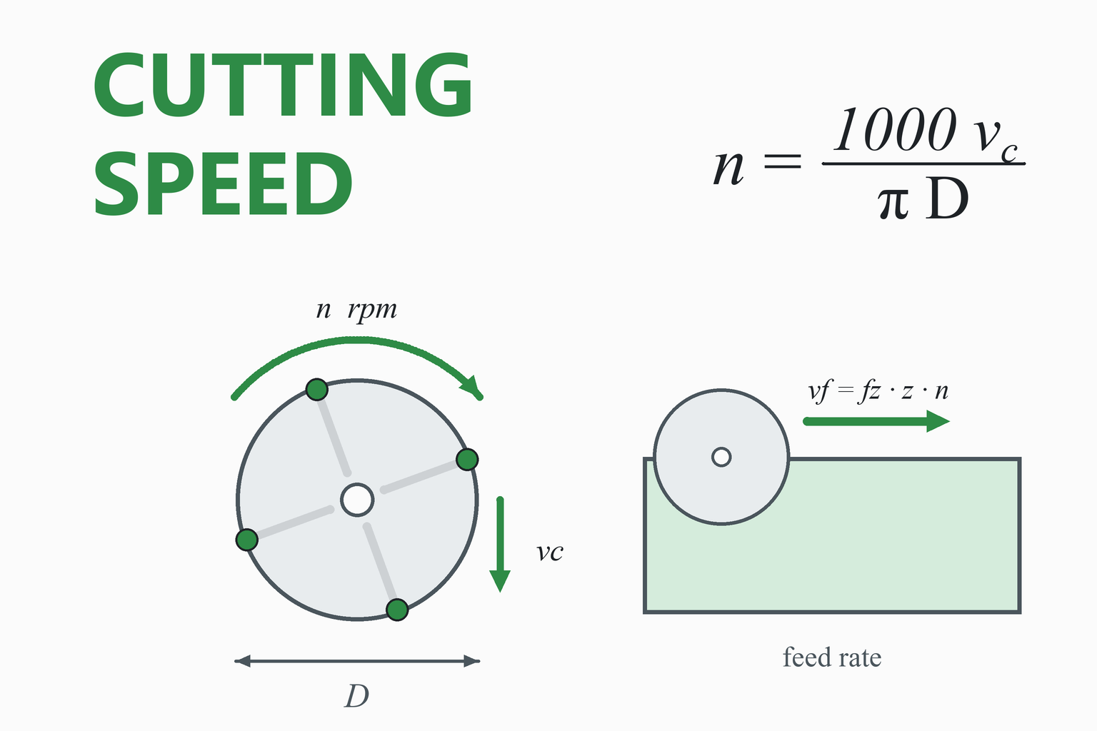
Every cutting tool has a speed at which its edge should move through the metal, called the cutting speed (or surface speed), and the tool maker or a machining handbook gives it in metres per minute or in surface feet per minute (SFM). The machine, though, is set in revolutions per minute. Turning one into the other depends on the diameter, and getting it wrong breaks tools or wastes time. This calculator converts in both directions, then works out the feed per tooth, feed per revolution and feed rate that go with that speed and the cutting time for a given length of cut. It also checks the result against the maximum speed of your spindle and shows what cutting speed you can really reach.
Cutting Speed and RPM Calculator
Cutting speed comes from the tool maker or a handbook · this calculator does not choose it for you
How the speed changes with diameter
—
Educational and planning tool. The calculator turns the speeds and feeds you choose into machine settings and times. It does not know your material, tool, coolant, machine rigidity or the tool life you need, and it does not check cutting forces, power or chatter.
Take the cutting speed and feed range from the tool maker’s catalogue or data sheet for your exact tool and workpiece material, start at the low end on unfamiliar jobs, and respect the maximum speed marked on the tool and on the spindle and chuck.
How to Use the Calculator
- Choose the operation and the units. Milling uses the cutter diameter, turning the diameter of the workpiece at the cut, and drilling the drill diameter.
- Pick what you want to find. Normally you know the cutting speed from the tool data and want the rpm. If you only know the rpm the machine is set to, switch to “cutting speed from a spindle speed” to see how fast the edge is moving.
- Enter the feed. In milling give the feed per tooth and the number of teeth (or the table feed); in turning and drilling give the feed per revolution (or the feed rate). The calculator fills in the rest.
- Add a length of cut to get the cutting time, and your machine’s top spindle speed to see whether it can reach the speed you want. If it cannot, the results use the machine limit and tell you the cutting speed you will really get.
Tip: for a quick estimate in your head, the spindle speed in rpm is about 318 times the cutting speed in m/min divided by the diameter in mm, or about 3.82 times the SFM divided by the diameter in inches.
Worked Examples
1. Milling with an end mill
Problem. A 10 mm end mill with 3 flutes is recommended to run at a cutting speed of 150 m/min with a feed of 0.05 mm per tooth. How fast should the spindle turn, what is the feed rate, and how long does a 300 mm tool path take?
- Spindle speed
n = 1000 vc / (π D) = 1000 × 150 / (π × 10) = 4,775 rpm
- Feed rate
vf = fz × z × n = 0.05 × 3 × 4,774.6 = 716.2 mm/min
- Cutting time
Tc = L / vf = 300 / 716.2 = 0.419 min = 25.1 s
2. Turning a bar
A 50 mm bar is turned at 200 m/min with a feed of 0.2 mm per revolution over 80 mm, on a lathe whose top speed is 3,000 rpm. The spindle speed is n = 1000 × 200 / (π × 50) = 1,273 rpm, below the limit. The feed rate is 0.2 × 1,273 = 254.6 mm/min, so the cut takes 80 / 254.6 = 0.314 min, or 18.8 s.
3. Drilling a hole
A 20 mm drill runs at 200 m/min with a feed of 0.20 mm per revolution into a hole 50 mm deep. The spindle speed is 1000 × 200 / (π × 20) = 3,183 rpm and the penetration rate is 0.20 × 3,183 = 636.6 mm/min. With the 118° drill point (0.300 D = 6.0 mm) added to the depth, the drill has to travel 56.0 mm, which takes 56.0 / 636.6 = 0.088 min, about 5.3 s.
4. Imperial units
A ½ in four-flute end mill is run at 400 SFM with 0.002 in per tooth. The spindle speed is n = 12 × 400 / (π × 0.5) = 3,056 rpm and the feed rate is 0.002 × 4 × 3,056 = 24.4 in/min. A 12 in tool path takes 12 / 24.4 = 0.49 min, about 29.5 s.
5. The machine cannot reach the speed
A 3 mm drill should run at 80 m/min, which needs 1000 × 80 / (π × 3) = 8,488 rpm, but the spindle tops out at 6,000 rpm. At 6,000 rpm the edge speed is π × 3 × 6,000 / 1000 = 56.5 m/min, 71% of the target. With a feed of 0.05 mm per revolution the penetration rate is 300 mm/min. Small drills are the usual place where the spindle, not the tool, sets the limit.
The Formulas
Cutting speed and spindle speed
vc is the cutting speed in m/min, D the diameter in mm and n the spindle speed in rpm. In imperial units, vc = π D n / 12 in ft/min (SFM) with D in inches, and n = 12 vc / (π D). They are the same relation: the edge travels once round the circumference πD every turn.
| Quantity | Symbol | Formula |
|---|---|---|
| Spindle speed | n | 1000 vc / (π D) ≈ 318.3 vc / D (metric); 12 vc / (π D) ≈ 3.82 vc / D (imperial) |
| Feed rate in milling | vf | fz × z × n |
| Feed per tooth | fz | vf / (n × z) |
| Feed per revolution | fn | vf / n (and fz × z in milling) |
| Feed rate in turning and drilling | vf | fn × n |
| Machining time | Tc | length of cut / vf |
| Drill point length (118°) | (D / 2) / tan(59°) = 0.300 D |
These are the standard relations published by cutting-tool makers for milling, turning and drilling. Keep the units consistent: with vc in m/min, D in mm and feed in mm, the rpm and the feed rate in mm/min come out directly.
Where the cutting speed comes from
The right cutting speed depends on the workpiece material, the tool material and coating, whether coolant is used, how rigid the setup is, the cut (roughing or finishing) and the tool life you want. It is not a property that can be calculated; it is read from the tool maker’s catalogue, the data sheet that comes with the tool, or a machining handbook. As a rough guide, carbide tools are generally run several times faster than high-speed steel (published rules of thumb say two to four times), and soft, free-cutting materials such as aluminium can be cut much faster than steel, stainless steel or titanium. Published tables for the same material can differ widely, which is another reason to use the data for your tool, and to start at the low end of the range on a new job.
Feed per tooth and chip thickness
The feed per tooth sets how thick a chip each tooth takes. Too little and the edge rubs instead of cutting, which wears it and heats the work; too much and the tooth or the machine is overloaded. Tool makers give a range for each cutter and material. When the radial depth of cut is less than half the cutter diameter, the chip is thinner than the feed per tooth, and the feed can be raised to compensate; the maker’s formulas cover this.
Turning and facing
In turning, D is the diameter of the workpiece at the point being cut, not the size of the tool. When you face a bar or turn a taper, the diameter changes as you cut, so a fixed spindle speed gives a changing cutting speed. Many CNC lathes can hold the surface speed constant by raising the rpm as the diameter falls, up to a spindle limit; the chart shows how steeply the rpm climbs for small diameters.
Drilling
The cutting speed of a drill is highest at the outer edge and falls to zero at the centre, and the value in the tables refers to the outer diameter. Small drills need very high rpm to reach a useful cutting speed, which is why a machine’s top speed so often limits them. To drill a blind hole to full diameter, the tip of the drill has to travel past the depth by the length of the point, 0.30 D for a 118° point.
Ball-nose and round-insert cutters
On a ball-nose end mill or a cutter with round inserts, the diameter that actually cuts depends on the depth of cut: a shallow cut works on a small diameter near the tip, where the cutting speed is low. For these tools use the effective cutting diameter at your depth of cut in the calculator, as the tool makers do, or the real cutting speed will be lower than you intend.
Common Mistakes
Confusing rpm with cutting speed
The rpm is a machine setting; the cutting speed is how fast the edge moves. The same rpm gives a different cutting speed on every diameter.
Mixing units
m/min with inches, or SFM with millimetres, gives a wrong answer by a factor of about 3 or 25, or both. Pick one system and check the labels.
Using the wrong diameter
In turning it is the workpiece diameter, not the insert. For ball-nose cutters it is the effective diameter at the depth of cut.
Counting the wrong teeth
The feed rate uses the number of cutting teeth, flutes or inserts on the cutter. A four-flute end mill with two flutes in the cut does not change z.
Ignoring the spindle limit
Small tools often need more rpm than the machine has. Check the real cutting speed and adjust the feed.
Using a table instead of the tool data
Generic speed tables differ widely. Use the recommendation for your exact tool, grade and material.
Assumptions and Limitations
- You supply the cutting speed and the feed. The calculator has no material or tool database.
- No forces, power or tool life. It does not check that the machine has the power or rigidity for the cut, or how long the tool will last.
- Constant diameter. Facing, tapers and profiles change the diameter during the cut; the result applies to the diameter you enter.
- Straight feed. The cutting time is the tool path length divided by the feed rate, with no acceleration, tool changes, rapid moves or arcs (where the feed at the tool edge differs from the feed at the tool centre).
- Drill point. The allowance assumes a 118° point and a hole drilled to full diameter; other point angles differ.
How This Calculator Was Verified
The formulas are those given on the machining formula pages of a major cutting-tool maker for milling, turning and drilling. The results were compared with an independent Python implementation over 3,000 random cases (milling, turning and drilling, both directions, with and without a spindle limit, metric and imperial). The reference uses the imperial formulas directly for imperial inputs, while the page converts to metric first, so the unit conversions are checked as well; the two agree to rounding error. The page also checks itself live:
| Check | Expected | Calculator |
|---|---|---|
| 100 mm face mill at 400 rpm | vc = π × 100 × 400 / 1000 = 125.66 m/min | … |
| Turning 50 mm at 700 rpm, 0.2 mm/rev | vc = 109.96 m/min; feed rate 140 mm/min | … |
| Drill 20 mm, 200 m/min, 0.20 mm/rev, 50 mm deep | 3,183.1 rpm; 636.6 mm/min; 0.0785 min | … |
| End mill 10 mm, 3 flutes, 150 m/min, 0.05 mm/tooth, 300 mm | 4,774.6 rpm; 716.2 mm/min; 25.1 s | … |
| ½ in, 4 flutes, 400 SFM, 0.002 in/tooth | 3,055.8 rpm; 24.45 in/min | … |
| Drill 3 mm, 80 m/min, spindle limit 6,000 rpm | needs 8,488 rpm; at 6,000 rpm the real vc is 56.5 m/min | … |
| Same cutter in both unit systems: 63.5 mm = 2.5 in at 100 m/min = 328.08 SFM | 501.275 rpm and 250.64 mm/min both ways | … |
The “Calculator” column is computed live, by the same code that runs the calculator, in your browser. The face-mill and turning checks use the same figures that appear in published worked examples.
Frequently Asked Questions
What is cutting speed?
Cutting speed, also called surface speed, is how fast the cutting edge moves through the material, measured at the outer edge of the tool or workpiece. It is given in metres per minute (m/min) or in surface feet per minute (SFM). It is a property of the tool, material and process, while the spindle speed in rpm is the machine setting you choose to achieve it.
How do I calculate rpm from cutting speed?
Divide the cutting speed by the circumference of the tool or workpiece. In metric units n = 1000 × vc / (π × D), with vc in m/min and D in mm, which is about 318 × vc / D. In imperial units n = 12 × SFM / (π × D), with D in inches, which is about 3.82 × SFM / D.
What is the formula for cutting speed?
vc = π × D × n / 1000 in m/min, with D in mm and n in rpm, or vc = π × D × n / 12 in ft/min with D in inches. For example, a 100 mm cutter at 400 rpm has a cutting speed of π × 100 × 400 / 1000 = 125.7 m/min.
What is the difference between SFM and m/min?
Both measure cutting speed. One metre is 3.281 feet, so a speed in m/min multiplied by 3.281 gives SFM, and a speed in SFM multiplied by 0.3048 gives m/min. For example, 100 m/min is 328 SFM. Take care not to mix them with diameters in the other system.
How do I find the right cutting speed for my material?
Use the data from the maker of your tool: the catalogue or data sheet lists a recommended cutting speed (often as a range) for each tool grade and workpiece material, together with the feed. Machining handbooks and speed-and-feed tables give typical values for common materials, but they vary widely between sources, so treat them as a starting point and begin at the low end of the range for unfamiliar jobs.
How do I calculate the feed rate for milling?
The feed rate (table feed) is the feed per tooth times the number of teeth times the spindle speed: vf = fz × z × n. For a 10 mm, 3-flute end mill at 4,775 rpm with 0.05 mm per tooth, vf = 0.05 × 3 × 4,775 = 716 mm/min. In turning and drilling the feed rate is the feed per revolution times the spindle speed.
What is feed per tooth, or chip load?
Feed per tooth (fz), often called chip load, is how far the cutter advances for each tooth as it turns. It sets the thickness of the chip each tooth removes. Tool makers recommend a range for each cutter and material; too little makes the edge rub and wear, too much overloads the tooth.
What happens if the spindle speed is too high or too low?
Too high a speed overheats the edge and shortens tool life, and may exceed the safe speed of the tool or work. Too low a speed wastes time and, together with a feed that is too small, can make the tool rub instead of cut. The recommended speed is a balance between productivity and tool life for the given tool and material.
Why does the spindle speed go up as the diameter goes down?
For the same cutting speed, a smaller circle has a shorter circumference, so the edge must go round more times a minute to cover the same distance. The rpm is inversely proportional to the diameter: half the diameter needs twice the rpm. That is why small drills and end mills need very high spindle speeds and why a facing cut on a lathe calls for rising rpm as the tool nears the centre.
How do I calculate the cutting time?
Divide the length the tool has to travel by the feed rate: Tc = L / vf. For a drill, include the length of the drill point (about 0.30 times the diameter for a 118° point) when the hole is drilled to full diameter. The result is the time the tool is cutting; it does not include tool changes, rapid moves or setup.
References and Further Reading
- Sandvik Coromant. Machining formulas and definitions (milling, general turning and drilling). (Cutting speed, spindle speed, feed rate, feed per tooth and machining time, in metric and imperial units.)
- Oberg, E., Jones, F. D., Horton, H. L., & Ryffel, H. H. Machinery’s Handbook. Industrial Press. (Cutting speeds and feeds for common materials and tools.)
- Kalpakjian, S., & Schmid, S. R. Manufacturing Engineering and Technology. Pearson. (Cutting speed, feed and depth of cut in machining processes.)
- The catalogue or data sheet of your tool maker, which gives the recommended cutting speed and feed range for each tool and workpiece material.