
Calculate the Factor of Safety of a Part, Simple or Combined Stress
Strength over stress, capacity over load, and the factor of safety for combined stresses by von Mises, Tresca and Coulomb–Mohr
The factor of safety tells you how much stronger a part is than it needs to be: the strength divided by the stress it actually carries, or the load it can take divided by the load it sees. A value of 1 means it is on the point of failing, and 2 means it could carry twice the load. This calculator works out the factor of safety in three ways: from a strength and a stress, from a capacity and a load, and for a combined stress state (normal stresses plus shear), where the right comparison is made by the von Mises or Tresca criterion for ductile metals and by the Coulomb–Mohr criterion for brittle ones. It also gives the margin of safety, the allowable stress for a required factor and a picture of where your stress sits against the failure limit.
Factor of Safety Calculator
Static loading · plane stress · strengths are the values you enter (use minimum values for design)
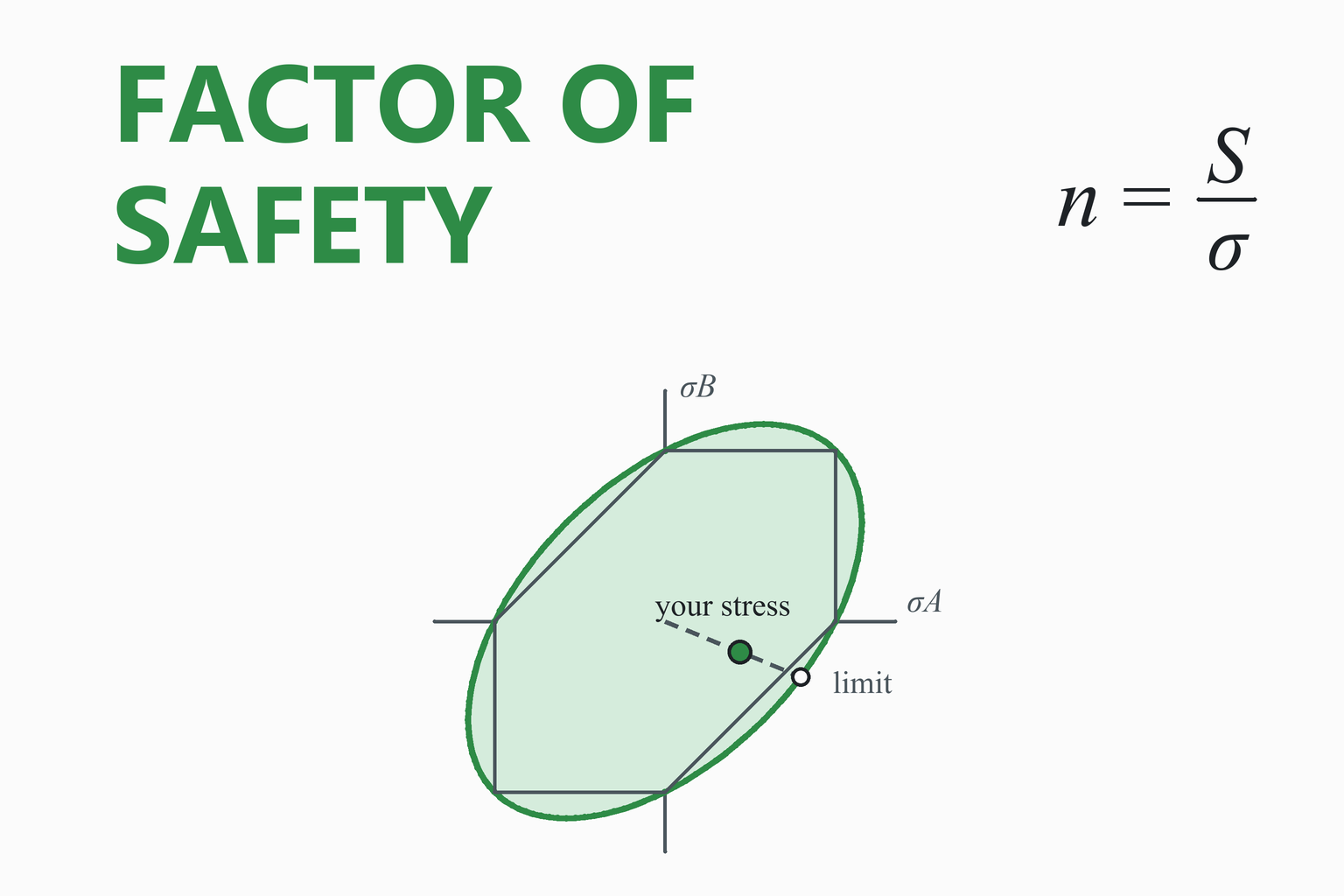
Where your stress sits against the limit
—
Educational and preliminary-design tool. A factor of safety is only as good as the strength and stress that go into it. This calculator covers static loading of a part at one point; it does not include fatigue, stress concentrations, buckling, creep or temperature, and it does not decide what factor you need.
Use minimum material properties for the grade you buy, follow the code or standard for your application, and have safety-critical designs checked by a qualified engineer.
How to Use the Calculator
- Choose the method. “Strength ÷ stress” if you already have one equivalent stress. “Capacity ÷ load” for a rated item such as a hook, shackle or chain. “Combined stresses” if the point carries normal and shear stress together, for example the surface of a shaft in bending and torsion.
- For combined stresses, enter σx, σy and τxy (tension positive) and the strengths. Pick “ductile” for most metals and “brittle” for cast iron, ceramics and similar materials.
- Add a required factor if you have a target. The calculator then reports the margin against it and, for the simple methods, the allowable stress or load.
- Read the chart. For combined stresses the dot is your stress state in the plane of the two principal stresses, and the shape is the failure limit. For the simple methods a bar shows how much of the strength is used.
Tip: the factor of safety is a number for one stress state at one point. A part has a factor of safety for each critical point and for each failure mode, and the smallest one governs.
Worked Examples
1. Strength over stress
A part of a steel with a yield strength of 350 MPa carries a stress of 175 MPa, and you want a factor of at least 1.5.
The part has a factor of 2.0, comfortably above the target.
2. Capacity over load
A lifting hook is rated to a breaking load of 50 kN and the heaviest load it will carry is 18 kN. The factor of safety is 50 / 18 = 2.78. If a factor of 2 is required, the greatest allowable load is 50 / 2 = 25 kN.
3. Combined stresses in a ductile metal
Problem. At a critical point of a steel part with Sy = 350 MPa, the stresses are σx = 120 MPa, σy = −40 MPa and τxy = 50 MPa. Find the factor of safety against yielding.
- Principal stresses.
σA,B = (120 − 40)/2 ± √(((120 + 40)/2)² + 50²) = 40 ± 94.34 = 134.34 and −54.34 MPa
- Von Mises stress.
σ′ = √(σA² − σAσB + σB²) = √(18,047 + 7,300 + 2,953) = 168.2 MPan = Sy / σ′ = 350 / 168.2 = 2.08
- Tresca (maximum shear) for comparison. The largest and smallest principal stresses, counting the zero out of the plane, are 134.34 and −54.34 MPa:
σ1 − σ3 = 188.7 MPa n = 350 / 188.7 = 1.86
Result: the von Mises factor of safety is 2.08 and the more conservative Tresca value is 1.86. Comparing the largest normal stress alone (134 MPa) with the yield strength would have given 2.6 and hidden the effect of the shear.
4. A brittle material
A grey cast iron part (tensile strength 214 MPa, compressive strength 752 MPa) carries σx = 60 MPa, σy = −90 MPa and τxy = 30 MPa. The principal stresses are 65.8 and −95.8 MPa. The maximum normal stress criterion gives n = min(214 / 65.8, 752 / 95.8) = 3.25. The Coulomb–Mohr criterion, which allows for the fact that tension and compression act together, gives 1 / n = 65.8 / 214 + 95.8 / 752, so n = 2.30.
What the Factor of Safety Means
Definitions
The factor of safety n compares what the part can take with what it takes. The margin of safety MS is a related number, used in aerospace and elsewhere, that is zero when the part just meets its requirement and positive when it exceeds it. Some write the margin of safety as n − 1, which is the same thing when the required factor is 1.
Two definitions that are not the same
A factor of safety on stress and a factor of safety on load agree only if stress is proportional to load. For a part in direct tension or in bending that is true, so doubling the load doubles the stress and the two are the same. When the stress depends on the load in a non-linear way (a column that buckles, a bolted joint, a part whose geometry changes under load), a factor on load is the more honest one. Always say which one you are quoting.
How much do you need?
The factor a design needs is set by what is known and what is at stake. Loads that are well known, material data that is measured and checked, a conservative analysis, and mild consequences of failure justify a low factor. Uncertain loads, scatter in the material, an approximate analysis, a brittle material or severe consequences call for more. Many design codes specify a minimum somewhere between about 1.5 and 3, and aircraft structures use a factor of 1.5 on limit load, but the values depend on the field and the code, and you should follow the one that applies to you. This calculator does not recommend a value.
Combined stresses and failure criteria
A real part rarely sees a single stress. At the surface of a shaft, bending gives a normal stress and torque a shear stress; in a pressure vessel there are hoop and axial stresses. To compare such a state with the strength measured in a simple tension test, the stresses are first reduced to principal stresses and then combined by a failure criterion:
| Criterion | Use for | Idea | Factor of safety (plane stress) |
|---|---|---|---|
| Von Mises (distortion energy) | Ductile metals | Yielding starts when the distortion energy reaches that of a tension test at yield | n = Sy / σ′, σ′ = √(σA² − σAσB + σB²) |
| Tresca (maximum shear) | Ductile metals, conservative | Yielding starts when the maximum shear stress reaches that of a tension test at yield | n = Sy / (σ1 − σ3), with σ3 = 0 out of the plane |
| Maximum normal stress | Brittle materials (simple) | Fracture when the largest normal stress reaches the strength | n = Sut / σA for tension, Suc / |σB| for compression |
| Coulomb–Mohr | Brittle materials, strong in compression | A straight-line envelope joining the tension and compression tests | 1/n = σA/Sut − σB/Suc when σA ≥ 0 ≥ σB |
The Tresca limit lies inside the von Mises limit; at most it is about 15% more conservative (the two agree for uniaxial tension and differ most for pure shear). For ductile steels the von Mises criterion fits test data better, and Tresca is used where simplicity or extra caution is wanted. The chart shows both for a plane stress state.
What a factor of safety does not cover
- Fatigue. A part that is loaded and unloaded repeatedly fails at stresses far below the static strength. Use the fatigue factor of safety calculator.
- Stress concentrations. Holes, shoulders and grooves raise the local stress. See the stress concentration factor calculator; for a ductile part under static load the effect may be ignored for strength, but for brittle materials and for fatigue it must be included.
- Buckling and deflection. Slender members in compression can buckle below the yield strength, and a part can be too flexible without being too weak.
- Bad data. If the strength used is a typical value and the real material is weaker, or the load is under-estimated, the calculated factor is an illusion. Use minimum properties and conservative loads.
Common Mistakes
Comparing a normal stress with yield and ignoring shear
When shear acts together with tension, the equivalent stress is higher than the largest normal stress. Use a failure criterion.
Using typical strengths
Handbook values are typical. For design use the minimum values of the grade and product form.
Static factor on a fatigue problem
A static factor of 3 can still fail a part loaded 10 million times. Check fatigue separately.
Mixing yield and ultimate
Use yield for ductile parts and ultimate for brittle ones. State which one your factor is on.
Treating 2 as a universal answer
The factor you need depends on the loads, the material, the analysis and the consequences, and codes often set it for you.
Checking one point only
Every critical point and every failure mode has a factor of safety. The smallest governs.
Assumptions and Limitations
- Static loading. Loads are applied once or slowly and do not repeat. Fatigue, impact and creep are not included.
- Plane stress. The combined mode uses σx, σy and τxy with no stress through the thickness. A full three-dimensional state needs the von Mises stress calculator.
- Isotropic material. The criteria assume the same strength in every direction. Composites and wood need other methods.
- The strengths are your input. The calculator does not know the grade or the temperature.
- One point, one mode. The result applies to the stress state you enter. It does not check buckling, joints, welds or deflection.
How This Calculator Was Verified
The results were compared with an independent Python implementation over 3,000 random plane-stress states. The reference finds the principal stresses from an eigen-decomposition of the stress matrix, the von Mises stress from the full tensor expression, and the factors of safety also numerically, by scaling the stress state and solving the failure criterion by bisection; the two agree to rounding error. The criteria were checked against their known limits: for equal biaxial tension the von Mises stress equals the stress, and for pure shear it is √3 times the shear stress. The page also checks itself live:
| Check | Expected | Calculator |
|---|---|---|
| Strength 350 MPa over stress 175 MPa, required 1.5 | n = 2.000; margin 0.333; allowable 233.3 MPa | … |
| Capacity 50 kN over load 18 kN, required 2 | n = 2.778; margin 0.389 | … |
| Principal stresses for 120, −40 and 50 MPa | 134.34 and −54.34 MPa; τmax 94.34 MPa | … |
| Von Mises for that state, Sy 350 MPa | 168.23 MPa; n = 2.081 | … |
| Tresca for that state | 188.68 MPa; n = 1.855 | … |
| Brittle state 60, −90 and 30 MPa; Sut 214, Suc 752 MPa | 65.78 and −95.78 MPa; maximum normal n = 3.253; Coulomb–Mohr n = 2.300 | … |
| Known limits of von Mises | equal biaxial 200 MPa: 200 MPa; pure shear 100 MPa: 173.2 MPa | … |
The “Calculator” column is computed live, by the same code that runs the calculator, in your browser. The cast-iron strengths in the example are typical values for a grey iron of about 30 ksi class, not data for a particular casting.
Frequently Asked Questions
What is the factor of safety?
It is the ratio of what a part can withstand to what it actually carries: the strength divided by the stress, or the failure load divided by the working load. A factor of 1 means the part is just on the point of failing and a factor of 2 means it could carry twice the load. It allows for uncertainty in the loads, in the material and in the analysis.
How do I calculate the factor of safety?
For a single stress, divide the strength of the material by the stress: n = S / σ, using the yield strength for a ductile part and the ultimate strength for a brittle one. For a rated item, divide its capacity by the load. If the stress is a combination of normal and shear stresses, first reduce it to an equivalent stress with a failure criterion such as von Mises, and then divide the yield strength by that.
What is the margin of safety, and how does it differ from the factor of safety?
The margin of safety is MS = n / nrequired − 1, where nrequired is the factor your requirement demands. It is zero when the part just meets the requirement and positive when it exceeds it. When the required factor is 1, the margin is simply n − 1. The two numbers carry the same information, but the margin of safety is the usual way to report a result against a requirement in aerospace work.
What factor of safety should I use?
It depends on how well the loads and the material are known, how accurate the analysis is, what happens if the part fails and what the applicable code requires. Many design codes specify a minimum between about 1.5 and 3, and aircraft structures use 1.5 on limit load, but there is no single right value. Follow the code for your application; this calculator does not recommend one.
Which failure criterion should I use for combined stresses?
For ductile metals use the von Mises (distortion-energy) criterion, which agrees best with test data for steels, or the more conservative Tresca (maximum shear) criterion. For brittle materials such as cast iron use the Coulomb–Mohr criterion, which accounts for their much greater strength in compression, or the simpler maximum normal stress criterion.
How do I find the principal stresses?
For plane stress with normal stresses σx and σy and shear stress τxy, the principal stresses are σA,B = (σx + σy)/2 ± √(((σx − σy)/2)² + τxy²). The shear stress is zero on those planes. The calculator shows them, the maximum shear stress and the direction of the principal planes.
Why is von Mises less conservative than Tresca?
The von Mises limit is an ellipse that passes through the corners of the Tresca hexagon, so it lies outside the hexagon between them. For uniaxial tension the two give the same answer, and for pure shear they differ most: Tresca predicts yield at a shear stress of half the yield strength, and von Mises at 0.577 of it, about 15% higher.
Does a factor of safety cover fatigue?
No. A static factor of safety compares the stress with the strength under a load applied once. A part loaded and unloaded many times can fail at a fraction of the static strength, so it needs a fatigue analysis that uses the endurance limit and the stress range, such as the Goodman method.
Can I use the calculator for a factor of safety on load?
Yes. In “Capacity ÷ load” mode enter the failure or rated load and the working load. A factor on load and a factor on stress are the same when stress is proportional to load, as in simple tension or bending, and differ when the response is non-linear, as in buckling.
What if the factor of safety is below 1?
It means that, by the criterion used, the stress state is outside the failure limit: the part is predicted to yield or fracture. Reduce the load, increase the section, use a stronger material or reduce the stress concentration, then recalculate.
References and Further Reading
- Budynas, R. G., & Nisbett, J. K. Shigley’s Mechanical Engineering Design. McGraw-Hill. (Static failure theories: maximum shear, distortion energy, Coulomb–Mohr and the design factor.)
- Norton, R. L. Machine Design: An Integrated Approach. Pearson. (Static failure and the factor of safety.)
- Hibbeler, R. C. Mechanics of Materials. Pearson. (Principal stresses, Mohr’s circle and the failure criteria.)
- Applicable design codes and standards for your field (structural, pressure vessel, lifting, aerospace): they set the required factors.