
Calculate Beam Deflection, Bending Moment and Stress
Simply supported, cantilever and fixed-end beams, with a point load, a uniform load and your own cross-section
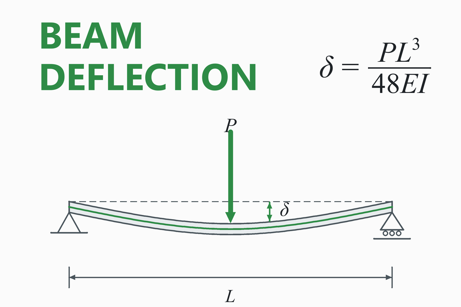
Beam deflection is how far a beam sags under load. It is set by the load, the span, the material stiffness E and the cross-section stiffness I. For a simply supported beam with a central load, the maximum deflection is PL³ ÷ 48EI. This calculator handles the three common support types, adds a point load (anywhere on the span) and a uniform load (including the beam’s own weight), builds the section properties for you, and returns deflection, bending moment, stress, reactions and a diagram.
Beam Deflection Calculator
Straight beam of constant section · linear elastic · small deflections · downward loads
| Span ÷ deflectionCompare with your limit, L/n | — |
|---|---|
| Deflection limit check | — |
| Second moment of area I | — |
| Flexural rigidity EI | — |
| Total uniform load | — |
| Reactions | — |
| Maximum bending moment | — |
| Maximum bending stress σ = M·c / I | — |
| Factor of safety against yield | — |
| At the chosen position | — |
Deflected shape and bending moment diagram
—
Educational and preliminary-design tool. It applies classical beam theory to an ideal beam. It does not include shear deformation, buckling (lateral-torsional or local), connections, axial loads, support settlement or dynamic effects.
For a structure, follow the applicable code (for example AISC or Eurocode) and have the design checked by a qualified engineer.
How to Use the Calculator
- Choose the support type and span. “Simply supported” means the ends can rotate freely; a cantilever is fixed at one end only; “fixed at both ends” stops both ends rotating. Real supports are rarely perfectly fixed, so treat the fixed results as the best case.
- Enter the loads. A single point load goes at position a from the left end. A uniform load w covers the whole span. You can use both: the calculator adds their effects. Tick the box to include the beam’s own weight.
- Describe the cross-section. Pick a shape and enter its dimensions, or enter I and the distance c to the outer fibre if you know them from a section table. Make sure the depth is the dimension in the direction of the load.
- Choose the material. Young’s modulus E sets the stiffness; yield strength is only used for the factor of safety.
- Read the results. Check the deflection against your limit first, then the bending stress. A beam must pass both: deflection (stiffness) and stress (strength).
Tip: Changing a unit drop-down converts the number in that field, so the physical value stays the same. The “SI / US customary” switch changes all units at once. Changing the support type moves the point load to the most common position (midspan, or the free end of a cantilever).
Worked Example: A Steel Beam with a Central Load
Problem. A solid rectangular steel bar, 50 mm wide and 100 mm deep, spans 2.0 m between two simple supports. It carries a 5 kN load at midspan. Find the maximum deflection, bending moment and stress, including the bar’s own weight. Use E = 200 GPa, ρ = 7850 kg/m³ and a yield strength of 250 MPa.
- Section properties. The 100 mm dimension is the depth.
I = b h³ / 12 = 0.050 × 0.100³ / 12 = 4.1667×10⁻⁶ m⁴EI = 200×10⁹ × 4.1667×10⁻⁶ = 833,333 N·m²
- Self-weight as a uniform load.
w = ρ g A = 7850 × 9.80665 × (0.050 × 0.100) = 384.9 N/m
- Deflection from the point load.
δP = P L³ / (48 E I) = 5000 × 2³ / (48 × 833,333) = 1.000 mm
- Deflection from the self-weight.
δw = 5 w L⁴ / (384 E I) = 5 × 384.9 × 2⁴ / (384 × 833,333) = 0.096 mm
- Total deflection (superposition: both are at midspan, so they add).
δmax = 1.000 + 0.096 = 1.096 mm → L/δ = 2000 / 1.096 = L/1824
- Maximum bending moment (at midspan).
Mmax = P L / 4 + w L² / 8 = 2500 + 192.5 = 2692 N·m
- Maximum bending stress at the top and bottom surfaces, where c = h/2 = 50 mm.
σ = M c / I = 2692 × 0.050 / 4.1667×10⁻⁶ = 32.3 MPaFactor of safety = 250 / 32.3 = 7.7
Result: δmax ≈ 1.10 mm (L/1824), Mmax ≈ 2.69 kN·m, σmax ≈ 32.3 MPa, with a factor of safety near 7.7 against yield. This beam is controlled by stiffness, not strength: if the deflection limit were tighter than L/1800, the bar would need a deeper section even though it is nowhere near yielding.
Same beam, same load, different supports
The support conditions change the answer more than almost anything else. The table uses the same 50 × 100 mm steel bar and the same 5 kN load, ignoring self-weight.
| Support condition | Maximum deflection | Relative to simply supported | Maximum bending moment |
|---|---|---|---|
| Fixed at both ends, load at midspan | 0.25 mm | ¼ | 1.25 kN·m |
| Simply supported, load at midspan | 1.00 mm | 1 | 2.50 kN·m |
| Cantilever, load at the free end | 16.0 mm | 16 | 10.0 kN·m |
Why such a big difference? Deflection grows with the cube of the effective span. A cantilever behaves like half of a simply supported beam that is twice as long and carries twice the load at its centre, which is why it deflects 16 times as much. Fixing the ends stops the end rotation and halves the maximum bending moment, so the beam bends much less.
What Is Beam Deflection and Why Does It Matter?
A beam carries load by bending. As it bends, its centreline moves away from the original straight position: that movement is the deflection. Beams are checked in two separate ways:
- Strength: is the bending stress below the stress the material can safely carry?
- Stiffness (serviceability): is the deflection small enough for the beam to do its job?
Many beams that are strong enough are still too flexible. A floor that sags cracks its plaster and feels bouncy. A machine frame that deflects throws gears and bearings out of alignment. A shelf that droops looks wrong long before it breaks. This is why the deflection check is as important as the stress check, and why, in practice, stiffness often decides the size of a beam.
The Theory in One Page
The calculator uses the classical Euler–Bernoulli beam theory. It assumes the beam is slender, the material is linear elastic, deflections are small and plane sections stay plane. Under those assumptions the bending moment M is proportional to the curvature of the beam:
Moment–curvature relation
y is the deflection, taken positive downward here. E is Young’s modulus and I is the second moment of area of the cross-section. The product EI is the beam’s flexural rigidity: its resistance to bending.
Differentiating once more gives the shear force V = dM/dx and the load q = dV/dx, so the whole chain is load → shear → moment → slope → deflection. The standard beam formulas come from integrating this chain with the boundary conditions of each support type.
Governing equation
Because the equation is linear, the effects of separate loads can be added. This is the principle of superposition, and it is how the calculator combines a point load with a uniform load.
Standard Beam Formulas
| Support and load | Maximum deflection | Where | Maximum moment |
|---|---|---|---|
| Simply supported, point load P at midspan | P L³ / (48 E I) | Midspan | P L / 4 |
| Simply supported, uniform load w | 5 w L⁴ / (384 E I) | Midspan | w L² / 8 |
| Cantilever, point load P at the free end | P L³ / (3 E I) | Free end | P L (at the wall) |
| Cantilever, uniform load w | w L⁴ / (8 E I) | Free end | w L² / 2 (at the wall) |
| Fixed at both ends, point load P at midspan | P L³ / (192 E I) | Midspan | P L / 8 (at the ends and at midspan) |
| Fixed at both ends, uniform load w | w L⁴ / (384 E I) | Midspan | w L² / 12 (at the ends) |
Two patterns are worth remembering. First, deflection always has the form (load) × (length)ⁿ ÷ EI: double the span and the deflection grows 8 times for a point load (L³) and 16 times for a uniform load (L⁴). Second, the beam gets stiffer when you add restraint: a uniform load on a fixed-fixed beam gives one fifth of the deflection of a simply supported beam (1/384 against 5/384).
A point load that is not at the centre
For a simply supported beam with a load P at distance a from the left support and b = L − a from the right, the reactions are P·b/L and P·a/L, the maximum moment is P·a·b/L under the load, and the deflection under the load is P·a²·b² / (3 E I L). The largest deflection is not under the load but a little toward the middle. It occurs at x = √((L² − b²)/3) from the left support (for a > b), and its value is P·b·(L² − b²)3/2 / (9√3 · E I L). The calculator finds this point for any position and any support type.
Section Properties: Why Depth Matters So Much
The second moment of area I measures how well the shape resists bending. For a rectangle, I = b·h³/12, with h the depth in the direction of the load. Depth enters as a cube: doubling the depth makes the beam 8 times stiffer, while doubling the width only doubles the stiffness. A plank laid on its edge is far stiffer than the same plank laid flat.
| Section | I | c |
|---|---|---|
| Solid rectangle, width b, depth h | b h³ / 12 | h / 2 |
| Solid circle, diameter d | π d⁴ / 64 | d / 2 |
| Round tube, outer do, inner di | π (do⁴ − di⁴) / 64 | do / 2 |
| Box section, outer b × h, wall t | [ b h³ − (b − 2t)(h − 2t)³ ] / 12 | h / 2 |
| I-section, depth h, flange width bf, flange tf, web tw | [ bf h³ − (bf − tw)(h − 2tf)³ ] / 12 | h / 2 |
The box and I-section formulas ignore the small corner radii and fillets of real rolled sections, so they give slightly lower values than a manufacturer’s table. For a standard rolled section, use the tabulated I and enter it with “Enter I and c directly”.
Bending Stress and the Factor of Safety
Flexure formula
Z = I/c is the section modulus. The stress is largest at the outer fibres, tension on one face and compression on the other, and zero on the neutral axis. The factor of safety against yield is Sy / σmax.
The stress depends on M and Z only, while the deflection depends on M, EI and the span. So two beams with the same section modulus can have very different deflections, and a higher-strength steel raises the allowable stress but does not make the beam any stiffer: all structural steels have almost the same E. If deflection controls, a stronger grade will not help; a deeper section will.
How Much Deflection Is Acceptable?
There is no single answer; the limit comes from the application. It is usually written as a fraction of the span, L/n. Building codes commonly use limits such as L/360 for floors and L/240 for roofs, with stricter values where brittle finishes are attached. Machine parts are often governed by alignment, gear-mesh or bearing requirements and can need much tighter limits. The calculator lets you enter n and shows whether the beam passes, but the limit itself must come from your code or specification.
Material Properties Used
| Material | E (GPa) | Density (kg/m³) | Yield Sy (MPa) |
|---|---|---|---|
| Structural steel (A36) | 200 | 7850 | 250 |
| Aluminium 6061-T6 | 68.9 | 2700 | 240 |
| Stainless steel 304 | 193 | 8000 | 205 |
Common Mistakes
Using the wrong axis
I depends on which way the beam bends. A 50 × 100 section has I = 4.17×10⁶ mm⁴ on edge but only 1.04×10⁶ mm⁴ laid flat, four times less.
Mixing units for I
mm⁴, cm⁴ and m⁴ differ by factors of 10⁴ and 10¹². A tabulated I in cm⁴ entered as mm⁴ is wrong by 10,000. Use the unit drop-down.
Forgetting self-weight
On a long, heavy beam the weight of the beam itself can be a large part of the load. Tick the self-weight box.
Assuming a perfectly fixed end
A real “fixed” end rotates a little. The fixed-fixed result is the best case; if the support is only partly stiff, the true deflection is larger.
Checking only stress
A beam can be far below yield and still sag too much. Always check the deflection limit as well.
Using the member length, not the span
The span is the distance between the supports, not the overall length of the piece.
Assumptions and Limitations
- Euler–Bernoulli theory: shear deformation is ignored. This is accurate for slender beams, but for short, deep beams (a span of roughly under ten times the depth) shear adds noticeably to the deflection and this calculator under-estimates it.
- Linear elastic, small deflections: valid while the stress is below yield and the deflection is small compared with the span.
- Constant cross-section and a straight, prismatic beam.
- One point load plus one uniform load over the whole span. Several loads or partial loads need a more general analysis or the superposition of several cases.
- Ideal supports: pinned/roller supports have no friction or settlement, and “fixed” supports are perfectly rigid.
- No buckling: a slender beam in compression flange can fail by lateral-torsional buckling, and thin-walled sections by local buckling, long before the bending stress reaches yield.
- Stress is the bending stress only. Shear stress, bearing stress at the supports and stress concentrations are not checked.
- Section formulas ignore corner radii and fillets; use catalogue values for standard rolled sections.
How This Calculator Was Verified
The formulas were checked two ways. First, the closed-form deflection and moment equations for all three support types, with point and uniform loads at random positions, were compared with an independent solution of the beam differential equation E·I·y⁗ = q obtained with the SymPy computer-algebra system. Over 700 test points in 18 random cases agreed to better than one part in 10¹². Second, the page’s own code is checked live against known textbook results:
| Check (50 × 100 mm steel, L = 2 m, EI = 833,333 N·m²) | Expected | Calculator |
|---|---|---|
| Simply supported, 5 kN at midspan | P L³ / 48EI = 1.000 mm | … |
| Simply supported, 1 kN/m uniform load | 5 w L⁴ / 384EI = 0.2500 mm | … |
| Cantilever, 5 kN at the free end | P L³ / 3EI = 16.00 mm | … |
| Cantilever, 1 kN/m uniform load | w L⁴ / 8EI = 2.400 mm | … |
| Fixed-fixed, 5 kN at midspan | P L³ / 192EI = 0.2500 mm; end moment P L / 8 = 1250 N·m | … |
| Fixed-fixed, 1 kN/m uniform load | w L⁴ / 384EI = 0.05000 mm; end moment w L² / 12 = 333.3 N·m | … |
| Simply supported, 5 kN at a = 0.5 m | P a (L² − a²)3/2 / (9√3 EI L) = 0.6988 mm at 0.882 m | … |
| Worked example with self-weight | δ = 1.0962 mm, M = 2692.5 N·m, σ = 32.31 MPa | … |
The “Calculator” column is computed live, by the same code that runs the calculator, in your browser.
Frequently Asked Questions
How do I calculate the deflection of a beam?
Find the second moment of area I of the cross-section, then use the formula for your support and load case. For a simply supported beam with a central point load P, the maximum deflection is PL³ / (48EI); with a uniform load w it is 5wL⁴ / (384EI). Loads can be added together (superposition) because the equations are linear.
What is the maximum deflection of a simply supported beam?
It depends on the load. A central point load gives PL³/(48EI) at midspan, and a uniform load gives 5wL⁴/(384EI) at midspan. A point load away from the centre gives a maximum slightly toward the middle of the beam rather than under the load.
What is flexural rigidity EI, and why must the units match?
EI, Young’s modulus multiplied by the second moment of area, is the beam’s resistance to bending. Deflection is inversely proportional to it. Because I has units of length to the fourth power, a mistake between mm⁴, cm⁴ and m⁴ changes the answer by a factor of 10,000 or more, so enter I in the unit you actually have.
How do I find I for a rolled section such as an I-beam?
Take it from the manufacturer’s section table and enter it with “Enter I and c directly”, together with c, which is half the depth for a symmetric section. The built-in I-section formula uses a simple shape with no fillets, so it slightly under-estimates a real rolled section.
What deflection limit should I use?
It depends on the application and the governing code. Building codes commonly use limits such as span/360 for floors and span/240 for roofs. Machine parts are usually governed by alignment, gear-mesh or bearing requirements and can need much stricter limits. Use the value your specification gives.
Does the beam’s own weight matter?
For long, heavy beams it can be a large fraction of the load. Tick the self-weight box and the calculator adds the weight per metre (density × gravity × area) to the uniform load. In the worked example it adds about 10% to the deflection.
Why is a fixed-fixed beam so much stiffer than a simply supported one?
Fixed ends cannot rotate, so they carry moment and take load away from the middle of the span. With a central point load the deflection is one quarter of the simply supported value, and with a uniform load it is one fifth. In practice real supports are never perfectly rigid, so the true values lie between the fixed and the simply supported results.
Does this include shear deformation, buckling or dynamic effects?
No. It uses classical Euler–Bernoulli beam theory for a slender, elastic, constant-section beam. Shear deformation matters for short, deep beams, and buckling, vibration and connection details need separate checks.
Can I use it for a load that is not at the centre, or for several loads?
You can place one point load anywhere along the span and combine it with a uniform load. For several point loads, run each load separately and add the deflections and moments at the same positions, because the results superpose.
References and Further Reading
- Gere, J. M., & Goodno, B. J. Mechanics of Materials. Cengage. (Deflections of beams; beam deflection tables.)
- Beer, F. P., Johnston, E. R., DeWolf, J. T., & Mazurek, D. F. Mechanics of Materials. McGraw-Hill.
- Hibbeler, R. C. Mechanics of Materials. Pearson.
- Budynas, R. G., & Nisbett, J. K. Shigley’s Mechanical Engineering Design. McGraw-Hill. (Beam deflection table in the appendix.)
- Young, W. C., Budynas, R. G., & Sadegh, A. M. Roark’s Formulas for Stress and Strain. McGraw-Hill.
- American Institute of Steel Construction. Steel Construction Manual: beam diagrams and formulas (Table 3-23).
- Timoshenko, S. Strength of Materials. (Shear deformation of beams.)
Related calculators: Shaft Diameter Calculator · Mohr’s Circle Calculator · Pipe Pressure Drop Calculator · All mechanical engineering calculators