
Calculate the Stress Concentration Factor Kt of a Shoulder, Hole or Notch
Shaft shoulder fillets in tension, bending and torsion, plates with holes, elliptical holes, and the fatigue factor Kf
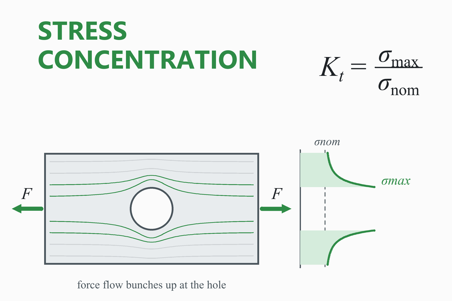
Every hole, shoulder, groove and keyway in a part concentrates stress: the peak stress at the feature is higher than the average stress around it. The ratio is the stress concentration factor, Kt = σmax ÷ σnom. It is what makes a shaft break at a sharp shoulder long before the smooth section would. This calculator gives Kt for a round shaft with a shoulder fillet (tension, bending and torsion), a plate with a central hole and an elliptical hole, turns it into the fatigue factor Kf with the notch sensitivity you choose, and finds the peak stress for your loads.
Stress Concentration Factor Calculator
Elastic stress · theoretical factor Kt from geometry alone · check the stated nominal stress for each case
How Kt changes with the geometry
—
Educational and preliminary-design tool. The shoulder-fillet values are published curve fits to chart data and are estimates; the plate and ellipse formulas assume ideal geometry and linear elastic material. Real parts have interacting features, residual stresses, surface finish and three-dimensional effects that these formulas do not capture.
For safety-critical parts, use the original charts or finite-element analysis, and have the design checked by a qualified engineer.
How to Use the Calculator
- Pick the feature. For a shaft with a step in diameter, choose the shoulder fillet. For a drilled plate use the circular hole, and for an oval opening use the elliptical hole.
- Enter the dimensions. For a shoulder, enter both diameters and the fillet radius. The ratio r/d and the step height drive the result, so an accurate radius matters most.
- Read Kt for each loading. A shaft shoulder has three different factors, for axial load, bending and torsion. They are not interchangeable.
- Add loads if you want the peak stress. The calculator computes the nominal stress that the factor is defined with, then multiplies it by Kt.
- For fatigue, set q. The result Kf is what the fatigue safety factor calculator asks for. If q is unknown, leave it at 1.
Tip: Watch the chart while you change the radius. Moving a dot to the right, to a larger r/d, is the cheapest way to cut a concentration: it costs nothing but a different tool radius.
Worked Example: A Shaft Shoulder in Bending
Problem. A steel shaft steps from D = 45 mm down to d = 30 mm with a fillet radius of 3 mm. It is loaded by a bending moment of 150 N·m at the shoulder. Find the stress concentration factors, the peak bending stress, and the fatigue factors for a material with notch sensitivity q = 0.85.
- Geometry ratios.
h = (D − d)/2 = 7.5 mm h/r = 7.5 / 3 = 2.5 r/d = 0.10 2h/D = 0.333
- Kt from the curve fits (h/r = 2.5 lies in the range 2 to 20 for tension and bending, and in 0.25 to 4 for torsion).
Kt (tension) = 1.86 Kt (bending) = 1.74 Kt (torsion) = 1.41
- Nominal bending stress at the small diameter.
σnom = 32 M / (π d³) = 32 × 150 / (π × 0.030³) = 56.6 MPa
- Peak stress at the fillet.
σmax = Kt σnom = 1.743 × 56.6 = 98.6 MPa
- Fatigue factors with q = 0.85.
Kf (bending) = 1 + 0.85 (1.743 − 1) = 1.63Kfs (torsion) = 1 + 0.85 (1.413 − 1) = 1.35
- What a bigger radius buys. Keeping everything else the same, bending Kt is 2.17 for r = 1.5 mm, 1.74 for r = 3 mm and 1.47 for r = 6 mm.
Result: the shoulder raises the bending stress from 56.6 MPa to about 98.6 MPa, with Kt ≈ 1.74 and fatigue Kf ≈ 1.63 for q = 0.85. A fillet twice as large would cut Kt by about 16%, which for a fatigue-limited shaft is often worth more than a stronger steel. The values Kf = 1.63 and Kfs = 1.35 can go straight into the fatigue calculator.
A plate with a hole
A 100 mm wide, 10 mm thick plate has a 20 mm hole on its centre line and carries 50 kN. The ratio is d/w = 0.2, so Kt (net section) = 3.00 − 3.14 × 0.2 + 3.667 × 0.2² − 1.527 × 0.2³ = 2.506. The net-section stress is 50,000 / (80 × 10) = 62.5 MPa, so the peak stress at the edge of the hole is 2.506 × 62.5 = 156.7 MPa. The average stress over the full width is only 50 MPa, so the hole has raised the peak to 3.13 times that, a gross-section factor of 3.13.
What Is Stress Concentration?
In a straight bar under tension the stress is uniform across any section. Cut a hole, a groove or a sharp step in it and that stops being true. The force still has to flow past the feature, and the lines of force crowd together around its edge, like water speeding up as a river narrows. The stress there rises sharply over a small region and falls back to the nominal value a short distance away.
Definition
The theoretical stress concentration factor Kt depends only on the shape and the type of loading, not on the material or the size, as long as the behaviour is elastic. The nominal stress must be calculated the way the source of the factor defines it, usually from simple formulas at the reduced section.
Because the factor depends on the ratios of dimensions (such as r/d), a tiny fillet on a big shaft concentrates stress just as much as a tiny fillet on a small one, once their ratios are the same. Sharp internal corners have a very large Kt in theory, which is why fatigue cracks so often start in fillets, grooves, keyway ends and thread roots.
The Shaft Shoulder Fillet
A shoulder where a shaft steps up in diameter, with a fillet radius r between the shaft and the shoulder face, is the most important stress raiser in machine design. Its Kt depends on three things: the step height h = (D − d)/2, the radius r, and the loading. The calculator uses published polynomial fits to the chart data (the charts of Peterson, in the form given by Pilkey):
Curve-fit form
The constants a, b and c depend on the loading and on the range of h/r. The nominal stresses are calculated at the small diameter d: σ = 4P/(πd²) for tension, 32M/(πd³) for bending and τ = 16T/(πd³) for torsion.
Show the coefficients used
| Loading and range | C1 | C2 | C3 | C4 |
|---|---|---|---|---|
| Tension, h/r 0.1 to 2 | 0.926, 1.157, −0.099 | 0.012, −3.036, 0.961 | −0.302, 3.977, −1.744 | 0.365, −2.098, 0.878 |
| Tension, h/r 2 to 20 | 1.200, 0.860, −0.022 | −1.805, −0.346, −0.038 | 2.198, −0.486, 0.165 | −0.593, −0.028, −0.106 |
| Bending, h/r 0.1 to 2 | 0.947, 1.206, −0.131 | 0.022, −3.405, 0.915 | 0.869, 1.777, −0.555 | −0.810, 0.422, −0.260 |
| Bending, h/r 2 to 20 | 1.232, 0.832, −0.008 | −3.813, 0.968, −0.260 | 7.423, −4.868, 0.869 | −3.839, 3.070, −0.600 |
| Torsion, h/r 0.25 to 4 | 0.905, 0.783, −0.075 | −0.437, −1.969, 0.553 | 1.557, 1.073, −0.578 | −1.061, 0.171, 0.086 |
The pattern is clear. Torsion gives the lowest Kt and tension the highest; a larger radius always helps; and a taller step makes things worse. The chart under the calculator shows the family of curves for your D/d.
A Hole in a Plate
The classical result for a small circular hole in a wide plate under uniform tension is Kt = 3: the stress at the sides of the hole is three times the stress far away, a result Kirsch derived in 1898. When the plate is not very wide compared with the hole, the stress at the hole edge is governed by the remaining ligament and the usual fit (Howland, as given by Peterson and Pilkey) is
Finite-width plate
based on the net-section stress σnom = P / ((w − d) t). Based instead on the average stress over the full width, Kt,gross = Kt / (1 − d/w), which grows as the hole gets larger.
The Elliptical Hole and the Crack
For an elliptical hole in a wide plate, Inglis showed in 1913 that the stress at the end of the axis lying across the load is σ(1 + 2a/b), where a is that semi-axis and b the one along the load. For a circle it gives 3. As the ellipse flattens into a slit across the load, a/b becomes large and so does the factor, which explains why a crack is far more dangerous than a round hole of the same length. In terms of the radius of curvature at the tip, ρ = b²/a, the factor is 1 + 2√(a/ρ). Drilling a round hole at the tip of a crack (a stop-hole) works by blunting that radius.
From Kt to Kf: Notches and Fatigue
In fatigue, many materials are less sensitive to a very sharp notch than Kt predicts, because the stress gradient is so steep that the peak acts only on a tiny volume. The fatigue stress concentration factor accounts for it with the notch sensitivity q:
Fatigue stress concentration factor
q = 0 means the notch has no fatigue effect and q = 1 means it acts at full Kt. Notch sensitivity grows with notch radius and with material strength, and is found from charts or empirical formulas in the textbooks. Use Kf for bending and axial loads and Kfs for torsion.
When to use Kt and when to ignore it
- Fatigue (repeated loading): always include the stress concentration, as Kf.
- Brittle materials under static load: include Kt, since there is no yielding to relieve the peak.
- Ductile materials under static load: the peak usually yields locally and redistributes, so Kt is often neglected for strength, but not for stiffness-critical or near-yield cases. Follow your code.
Practical Ways to Reduce Stress Concentration
| Measure | Why it works |
|---|---|
| Increase the fillet radius | Spreads the stress over a larger area; the single most effective change |
| Reduce the size of the step | A smaller change in section gives a gentler flow of force |
| Use a tapered or elliptical fillet, or an undercut relief groove | Lets a large effective radius fit where a plain large fillet would interfere with a bearing or gear seat |
| Add material-removing “relief” features near the notch | Makes the flow of force more gradual (stress-relief grooves, holes) |
| Keep features apart | Neighbouring holes, keyways and shoulders interact and raise each other’s peak |
| Improve the surface of the fillet | Smoother, shot-peened or cold-rolled fillets resist fatigue cracks better |
Common Mistakes
Using the wrong nominal stress
Kt goes with a defined nominal stress: the small diameter for a shoulder, the net section for a hole. Mixing them gives errors of 30% or more.
Using the bending factor for torsion
Tension, bending and torsion each have a different Kt at the same shoulder. Use the one that matches the load.
Using Kt where Kf belongs
For fatigue, apply the notch sensitivity. Using Kt alone is safe but may be over-conservative; ignoring the concentration is unsafe.
Assuming the drawing radius
A fillet radius “about 1 mm” on the drawing may come out smaller after wear of the tool. Check the real part.
Ignoring interacting features
A keyway close to a shoulder, or two holes close together, give a higher peak than either alone.
Treating stronger steel as the cure
The concentration depends on shape. A stronger steel is usually more notch sensitive, so it gains less than you hope.
Assumptions and Limitations
- Three cases only. Shoulder fillet in a round shaft, central circular hole in a plate, elliptical hole. Keyways, grooves, threads, transverse holes and stepped flat bars are not included.
- Curve fits, not exact solutions. The shoulder-fillet factors approximate chart data and are valid only for the h/r ranges given. The calculator warns when you leave them.
- Elastic and static geometry. Kt is a purely elastic result; plasticity, residual stress and surface condition are not included.
- Idealised loading. Single-mode loads (tension, bending or torsion) with the stated nominal stresses. Combined loading needs a stress analysis or the factors applied to each stress component, as in the fatigue calculator.
- Wide plate for the ellipse, with its axes aligned to the load.
- Notch sensitivity q is your input. It depends on the material, the notch radius and the loading.
How This Calculator Was Verified
I could not open the original charts here, so the checks are of three kinds. First, the shoulder-fillet coefficients were typed a second time, independently, and compared with the code over 5,000 random geometries for all three loadings (they agree to rounding error). Second, the fits are two coefficient sets that meet at h/r = 2; the two sets agree there to within 1% for step ratios up to D/d = 2.5 (0.3% for tension, 0.9% for bending), which would not happen if a coefficient were mistyped. Third, physical sanity checks: Kt rose as the fillet radius shrank in every one of 4,000 random trials, and tends to 1 for a huge radius. The plate-with-hole polynomial and the Inglis formula were compared with their closed forms, and the gross-section relation with the peak stress. The page also checks itself live:
| Check | Expected | Calculator |
|---|---|---|
| Elliptical hole, 1 + 2a/b | 3 for a circle; 5 for a/b = 2; 2 for a/b = 0.5 | … |
| Plate with hole, net section, d/w = 0.1, 0.2, 0.3, 0.5, 0 | 2.721, 2.506, 2.347, 2.156; 3.000 | … |
| Shoulder fillet, D/d = 1.5, r/d = 0.1 | about 1.74 (bending), 1.86 (tension), 1.41 (torsion) | … |
| Continuity of the two coefficient sets at h/r = 2 (2h/D from 0.05 to 0.6) | under 1% | … |
| Trends | about 1 for a huge radius; higher for a sharp radius | … |
| Fatigue factor, Kt = 2.5 | 1.00 (q = 0), 2.20 (q = 0.8), 2.50 (q = 1) | … |
The “Calculator” column is computed live, by the same code that runs the calculator, in your browser. The shoulder-fillet values should be treated as estimates of the published charts; compare with the chart for critical designs.
Frequently Asked Questions
What is a stress concentration factor?
It is the ratio of the peak stress at a notch, hole, shoulder or groove to the nominal stress that would exist there if the feature were not present: Kt = σmax / σnom. It depends only on geometry (and the type of loading), not on the material, as long as the material stays elastic.
What is the stress concentration factor of a hole in a plate?
For a small circular hole in a wide plate loaded in tension, Kt is 3: the stress at the edge of the hole is three times the stress far from it. For a hole in a plate of finite width, based on the net section, Kt = 3.00 − 3.14(d/w) + 3.667(d/w)² − 1.527(d/w)³, which falls from 3 toward about 2 as the hole grows.
How do I reduce the stress concentration at a shaft shoulder?
Use the largest fillet radius you can, since doubling the radius cuts Kt noticeably; reduce the step in diameter; make the transition gradual (a tapered or elliptical fillet, or undercut relief grooves); and keep other features such as keyways and holes away from the shoulder. For fatigue, surface treatments such as shot peening or cold rolling the fillet also help.
What is the difference between Kt and Kf?
Kt is the theoretical, geometry-only factor. Kf is the fatigue stress concentration factor that accounts for the material’s notch sensitivity q: Kf = 1 + q (Kt − 1). q lies between 0, where the material ignores the notch, and 1, where it feels the full Kt. Use Kf in fatigue calculations, and Kf = Kt if you do not know q.
Do I need to apply Kt to static loading?
Often not for ductile materials loaded statically: the material yields locally, redistributes the load and the concentration has little effect on strength. Apply Kt for brittle materials, for fatigue and for loading that is close to yield. Always follow the code or standard for your application.
Which nominal stress does Kt refer to?
It depends on the chart, so use the definition that goes with the formula. For the shaft shoulder here, the nominal stress is calculated at the smaller diameter d (4P/πd², 32M/πd³ or 16T/πd³). For the plate with a hole it is the net-section stress P/((w − d)t), and the gross-section value is shown too. Using the wrong nominal stress gives a wrong peak stress.
How accurate are the shoulder-fillet results?
They come from published curve fits to Peterson’s chart data, so they are estimates of the chart values, not exact answers, and they are valid only within the stated range of h/r. The calculator warns you when you leave the range. For critical parts, check the original chart or use finite-element analysis.
Why is the stress concentration of an elliptical hole 1 + 2a/b?
This is Inglis’ classical solution for an elliptical hole in a wide plate: the stress at the end of the axis across the load is σ(1 + 2a/b), where a is the semi-axis across the load and b the semi-axis along it. A circle (a = b) gives 3, and a thin slit across the load (large a/b) gives a very high value, which is why slits and cracks are so dangerous.
References and Further Reading
- Pilkey, W. D., & Pilkey, D. F. Peterson’s Stress Concentration Factors. Wiley. (Charts and formulas for plates with holes and for stepped shafts; Howland’s plate solution.)
- Pilkey, W. D. Formulas for Stress, Strain, and Structural Matrices. Wiley. (Curve fits for shoulder-fillet factors in tension, bending and torsion.)
- Young, W. C., Budynas, R. G., & Sadegh, A. M. Roark’s Formulas for Stress and Strain. McGraw-Hill. (Stress concentration factors.)
- Budynas, R. G., & Nisbett, J. K. Shigley’s Mechanical Engineering Design. McGraw-Hill. (Stress concentration, notch sensitivity and fatigue factors; charts in the appendix.)
- Inglis, C. E. “Stresses in a plate due to the presence of cracks and sharp corners.” Transactions of the Institution of Naval Architects, 1913.
- Kirsch, G. “Die Theorie der Elastizität und die Bedürfnisse der Festigkeitslehre.” 1898. (The circular hole in an infinite plate.)
- Neuber, H. Theory of Notch Stresses. (Notch effect and the notch sensitivity concept.)