
Calculate the Moment of Inertia (Second Moment of Area) of a Cross-Section
Rectangle, circle, tube, box, I-beam, T, channel, triangle, semicircle and your own composite shape
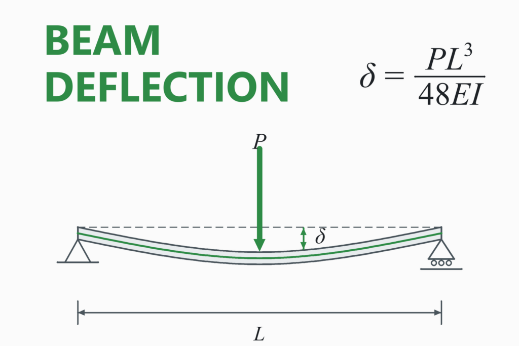
The moment of inertia of an area, also called the second moment of area, measures how a cross-section resists bending. It is the quantity I in the beam equations δ = PL³ ÷ 48EI and σ = M·c ÷ I. For a rectangle it is I = b·h³ ÷ 12. This calculator finds the area, centroid, Ix, Iy, polar moment, radius of gyration and section modulus of ten shapes, transfers I to any parallel axis, and builds composite sections from rectangles, with the principal axes when the shape is not symmetric.
Moment of Inertia Calculator
Second moment of area (mm⁴, in⁴), not mass moment of inertia · about the centroidal axes
| Area A | — |
|---|---|
| Centroid, horizontal position x̄From the left edge of the outline | — |
| Centroid, vertical position ȳFrom the bottom edge of the outline | — |
| Ix about the horizontal centroidal axis | — |
| Iy about the vertical centroidal axis | — |
| Polar moment of area J = Ix + IyAbout the centroid, perpendicular to the section | — |
| Radius of gyration rx = √(Ix/A) | — |
| Radius of gyration ry = √(Iy/A) | — |
| Distance to the top fibre ctop | — |
| Distance to the bottom fibre cbottom | — |
| Section modulus Sx = Ix/c, top fibre | — |
| Section modulus Sx = Ix/c, bottom fibre | — |
| Section modulus Sy, left edge | — |
| Section modulus Sy, right edge | — |
| Product of inertia Ixy | — |
| Principal moments I1, I2 and angleAngle of the I1 axis from the x axis | — |
| I about a parallel horizontal axisIx + A·d², d from the box above | — |
| I about a parallel vertical axisIy + A·d² | — |
The section, with its centroid and axes
—
Educational and preliminary-design tool. It returns the geometric properties of an ideal outline. Rolled sections have fillets and tapered flanges, which the I, channel and box formulas ignore; for a catalogue section, use the manufacturer’s tabulated values.
A section’s geometric properties are only one part of a design. Follow the applicable code and have structural work checked by a qualified engineer.
How to Use the Calculator
- Pick the shape and the unit. Choose the closest standard shape. Use “Composite” for anything else: L-angles, plates welded to a tube, a hollow shape with a slot, and so on.
- Enter the dimensions. The height h is the dimension in the direction of the load (vertical). The result Ix is for bending about the horizontal axis through the centroid.
- For a composite shape, list the rectangles. Choose one origin anywhere, then enter each rectangle’s width, height and the x and y position of its centre. Tick “Hole” to remove a rectangle. The calculator finds the centroid and applies the parallel-axis theorem for you.
- Read the results. Ix and Iy are about the centroid. Use the section modulus S for stress (σ = M/S) and the radius of gyration for column slenderness.
- Need I about another axis? Enter the distance in the parallel-axis box and read the transferred value.
Tip: Compare the two results Ix and Iy. If they are very different, the section is much stiffer one way than the other, so check that you have it oriented correctly before using it in a beam calculation.
Worked Example: A T-Section
Problem. A T-shaped bar has a flange 100 mm wide and 20 mm thick on top of a stem 20 mm wide, so the overall depth is 120 mm. Find the centroid, the second moment of area about the horizontal centroidal axis, and the section moduli.
- Split the shape into two rectangles and measure from the bottom of the stem.
Stem: 20 × 100 mm, area 2000 mm², centre at 50 mmFlange: 100 × 20 mm, area 2000 mm², centre at 110 mm
- Find the centroid (area-weighted average).
ȳ = (2000 × 50 + 2000 × 110) / 4000 = 80 mm from the bottom
- Apply the parallel-axis theorem to each rectangle. Both centres are 30 mm from the centroid (80 − 50 and 110 − 80).
Stem: I = 20 × 100³/12 + 2000 × 30² = 1,666,667 + 1,800,000 = 3,466,667 mm⁴Flange: I = 100 × 20³/12 + 2000 × 30² = 66,667 + 1,800,000 = 1,866,667 mm⁴
- Add them.
Ix = 3,466,667 + 1,866,667 = 5,333,333 mm⁴ = 5.333 × 10⁶ mm⁴
- Vertical axis. The T is symmetric about the vertical axis, so the centroid is at the middle of the flange, and no transfer term is needed.
Iy = 20 × 100³/12 + 100 × 20³/12 = 1,666,667 + 66,667 = 1,733,333 mm⁴
- Section moduli and radius of gyration. The top fibre is 120 − 80 = 40 mm from the centroid and the bottom fibre is 80 mm away.
Stop = 5,333,333 / 40 = 133,333 mm³Sbottom = 5,333,333 / 80 = 66,667 mm³rx = √(5,333,333 / 4000) = 36.5 mm
Result: the centroid is 80 mm above the bottom of the stem, Ix = 5.333 × 10⁶ mm⁴ and Iy = 1.733 × 10⁶ mm⁴. Because the centroid is not at mid-depth, the two section moduli differ (66,667 and 133,333 mm³). For the same bending moment the stress at the bottom of the stem is twice the stress at the top of the flange, since the bottom fibre is 80 mm from the neutral axis and the top fibre only 40 mm. Under a sagging moment the stem is in tension and the flange in compression, and the smaller modulus gives the larger stress.
Try the same T in the “Composite” mode: enter the stem as 20 × 100 with its centre at (50, 50) and the flange as 100 × 20 with its centre at (50, 110). You get the same answer.
The parallel-axis theorem in one line
A 100 × 200 mm rectangle has I = 66.67 × 10⁶ mm⁴ about its own centroid. About its bottom edge, 100 mm below the centroid, I = 66.67 × 10⁶ + 20,000 × 100² = 266.7 × 10⁶ mm⁴, exactly bh³/3. The transfer term A·d² dominates once the axis is far from the centroid, which is why the flanges of an I-beam, far from the middle, do most of the work.
What Is the Moment of Inertia of an Area?
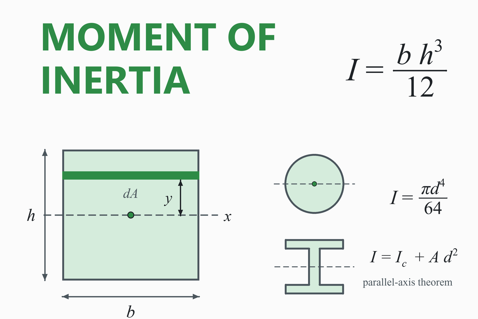
When a beam bends, the material far from the neutral axis is stretched or squeezed the most and carries the most stress. A cross-section whose material is spread far from the centre is therefore stiffer in bending than a compact one of the same area. The second moment of area puts a number on that. For an area A, about an axis x:
Definition
Every small piece of area dA counts in proportion to the square of its distance from the axis. The units are length to the fourth power (mm⁴, in⁴). The centroidal axes pass through the centroid, the area’s balance point.
The same quantity is also called the area moment of inertia or simply “I” in beam formulas. It enters the bending stress σ = M·c/I, the deflection equations (through EI) and the buckling load of columns.
Not the same as mass moment of inertia. The mass moment of inertia, in kg·m², describes how hard it is to spin an object (I = ∫ r² dm), and is used for flywheels, shafts and rotating parts. The area moment of inertia on this page, in m⁴, describes bending of a cross-section. They share a name and a similar integral but are different quantities with different units.
Standard Section Formulas
| Shape | Area A | Centroid | Ix (horizontal axis) | Iy (vertical axis) |
|---|---|---|---|---|
| Rectangle b × h | b h | h/2 | b h³ / 12 | h b³ / 12 |
| Solid circle, diameter d | π d² / 4 | d/2 | π d⁴ / 64 | π d⁴ / 64 |
| Hollow circle, do and di | π (do² − di²) / 4 | do/2 | π (do⁴ − di⁴) / 64 | same |
| Hollow rectangle B × H, wall t | B H − (B−2t)(H−2t) | H/2 | [B H³ − (B−2t)(H−2t)³] / 12 | [H B³ − (H−2t)(B−2t)³] / 12 |
| I-section, h, bf, tf, tw | 2 bf tf + (h−2tf) tw | h/2 | [bf h³ − (bf−tw)(h−2tf)³] / 12 | [2 tf bf³ + (h−2tf) tw³] / 12 |
| Triangle, base b, height h (isosceles) | b h / 2 | h/3 | b h³ / 36 | h b³ / 48 |
| Semicircle, radius r | π r² / 2 | 4r / (3π) | (π/8 − 8/(9π)) r⁴ ≈ 0.1098 r⁴ | π r⁴ / 8 |
The T and channel shapes are built from rectangles with the parallel-axis theorem below, so they follow from the composite method. Notice the exponents: doubling the height of a rectangle multiplies Ix by 8, while doubling the width only doubles it. Doubling a circle’s diameter multiplies I by 16.
The Parallel-Axis Theorem
Transfer to a parallel axis
Ic must be about the centroidal axis, A is the area and d is the distance between the two parallel axes. The centroidal value is always the smallest, and the transfer term is always positive.
The theorem is the key to every composite section. It also explains why an I-beam is efficient: the web contributes little to I but connects the two flanges, each of which gets a large A·d² term because it sits far from the neutral axis.
Composite Sections Step by Step
- Split the shape into simple parts whose own centroids and moments are known (rectangles are enough for most shapes). Treat holes as parts with negative area.
- Choose an origin and find the centroid: x̄ = Σ(Ai xi) / ΣAi and ȳ = Σ(Ai yi) / ΣAi.
- Transfer each part to the centroid: Ix = Σ[ Ixi + Ai (yi − ȳ)² ], and the same for Iy. Subtract the terms of holes.
- If the shape is not symmetric, also find the product of inertia Ixy = Σ Ai (xi − x̄)(yi − ȳ). It is zero when either centroidal axis is an axis of symmetry.
Principal axes
For an unsymmetric section such as an angle, bending is cleanest about the principal axes, where Ixy = 0 and I takes its largest and smallest values: I1,2 = (Ix + Iy)/2 ± √[ ((Ix − Iy)/2)² + Ixy² ], at the angle tan 2θ = −2Ixy / (Ix − Iy). The mathematics is identical to Mohr’s circle for stress, with Ix, Iy and Ixy in place of σx, σy and τxy.
The sign of Ixy depends on the axis directions (x to the right, y up here). The principal values do not depend on it, but the angle does, so check the sign convention of your textbook if you compare angles.
Section Modulus and Radius of Gyration
Section modulus S = I/c turns the bending moment into the peak stress: σmax = M/S. A section that is not symmetric has two values, one for the top and one for the bottom fibre; the smaller one gives the higher stress. Section modulus has units of length cubed.
Radius of gyration r = √(I/A) is the distance from the axis at which the whole area could be concentrated and still give the same I. Columns use it in the slenderness ratio L/r, and the weaker axis, the smaller r, governs buckling.
Polar Moment of Area
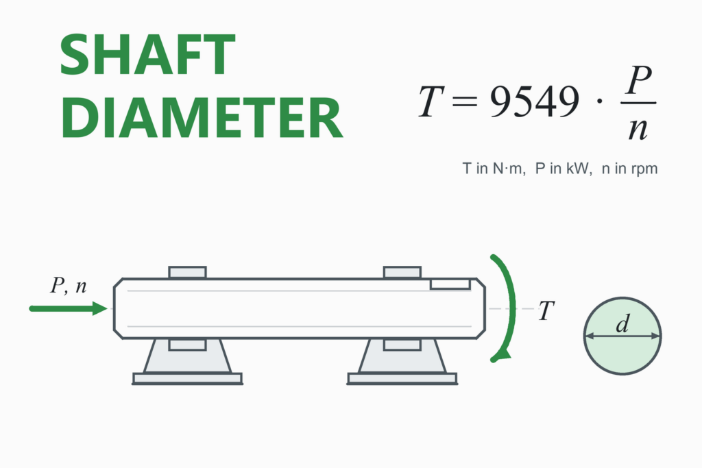
For any planar shape, the polar moment of area about the centroid is J = Ix + Iy (the perpendicular-axis theorem). For a solid or hollow circle this J is also the torsion constant used in τ = T·r/J and the twist angle, which is why J = πd⁴/32 appears in shaft design. For any other shape, J = Ix + Iy is not the torsion constant: rectangles, boxes and open sections twist very differently from the polar moment, and need a different torsion formula.
Common Mistakes
Using the wrong axis
A 50 × 100 bar has I = 4.17×10⁶ mm⁴ on edge but only 1.04×10⁶ mm⁴ laid flat. The load direction decides which one you need.
Mixing units
1 in⁴ is 416,231 mm⁴ and 1 cm⁴ is 10,000 mm⁴. A value taken from a table in cm⁴ and entered as mm⁴ is wrong by 10,000.
Transferring from a non-centroidal axis
The parallel-axis theorem only works from the centroid. Moving from one off-centre axis to another needs two steps: back to the centroid, then out again.
Mass vs area moment of inertia
The kg·m² value used for rotation is a different quantity from the m⁴ value used for bending.
Forgetting to subtract holes
In a composite section, a hole contributes negative area and a negative moment. Leaving it out over-estimates both A and I.
Using J as a torsion constant
J = Ix + Iy equals the torsion constant only for circular sections.
Assumptions and Limitations
- Ideal geometry: sharp corners and constant wall thickness. Fillets, taper and rounded edges are ignored, so rolled I-beams and channels come out a little low. Use catalogue values for those.
- Isosceles triangle: Iy assumes the apex is above the middle of the base.
- Channel and T: the flanges have a constant thickness, and the T is symmetric about the vertical axis.
- Composite mode uses axis-aligned rectangles only. Inclined parts, curves and tapered shapes need to be split into rectangles or handled with a drawing program.
- Geometric properties only. Local buckling, shear, torsion and fatigue of the section are not evaluated.
How This Calculator Was Verified
Every closed-form result was compared with an independent numerical method: the section outline was treated as a polygon (circles and semicircles with tens of thousands of segments) and its area, centroid and moments were computed by Green’s theorem, which uses no shape formulas at all. 3,000 random sections of all ten types agreed to better than one part in 10⁹ (the polygon approximation of circles limits the agreement; the straight-edged shapes agree to about 10¹⁵). The page’s own code is also checked live against hand-calculable cases:
| Check | Expected | Calculator |
|---|---|---|
| Rectangle 100 × 200 mm | Ix = 66.667×10⁶ mm⁴, Iy = 16.667×10⁶ mm⁴ | … |
| Solid circle, d = 100 mm | πd⁴/64 = 4.9087×10⁶ mm⁴ | … |
| Tube 100 mm outer, 80 mm inner | π(100⁴ − 80⁴)/64 = 2.8981×10⁶ mm⁴ | … |
| I-section h = 200, bf = 100, tf = 10, tw = 6 mm | Ix = 20.9827×10⁶ mm⁴, Iy = 1.6699×10⁶ mm⁴ | … |
| T-section (worked example) | ȳ = 80 mm, Ix = 5.3333×10⁶ mm⁴ | … |
| The same T as two rectangles (composite) | ȳ = 80 mm, Ix = 5.3333×10⁶ mm⁴ | … |
| Triangle 120 × 180 mm | b h³/36 = 19.440×10⁶ mm⁴ at h/3 = 60 mm | … |
| Semicircle, r = 50 mm | 4r/3π = 21.221 mm; (π/8 − 8/9π) r⁴ = 685,981 mm⁴ | … |
| Rectangle 100 × 200 about its base | b h³/3 = 266.6667×10⁶ mm⁴ | … |
The “Calculator” column is computed live, by the same code that runs the calculator, in your browser.
Frequently Asked Questions
What is the moment of inertia of a beam cross-section?
It is the second moment of area, I = ∫y² dA: a number that measures how well the shape resists bending, with units of length to the fourth power (mm⁴ or in⁴). It appears in the flexure formula σ = M·c/I and in the deflection equations through the flexural rigidity EI. A bigger I means a stiffer beam.
What is the moment of inertia of a rectangle?
About the horizontal axis through the centroid it is I = b·h³/12, where h is the height in the direction of bending, and about the vertical centroidal axis it is h·b³/12. About the bottom edge it is b·h³/3, found with the parallel-axis theorem.
What is the difference between area moment of inertia and mass moment of inertia?
The area (second) moment of inertia, in m⁴, describes how a cross-section resists bending. The mass moment of inertia, in kg·m², describes how hard it is to change the rotation of a body, as in flywheels and rotating shafts. They are different quantities. This page calculates the area moment.
How do I find the moment of inertia of an I-beam or any composite shape?
Split the shape into rectangles, find the centroid of the whole shape by area-weighting the parts, then add each part’s own I about its centroid plus A·d², where d is the distance from the part’s centroid to the overall centroid. Subtract holes. The composite mode does exactly this. For a standard rolled I-beam, use the tabulated value, which includes the fillets.
What is the parallel-axis theorem?
I = Ic + A·d². It moves the second moment of area from an axis through the centroid to a parallel axis a distance d away. The starting axis must pass through the centroid, and the result is always larger than Ic.
Why does the height of a beam matter so much more than its width?
Because I for a rectangle is b·h³/12: the depth is cubed and the width is not. Doubling the depth makes the beam eight times stiffer, doubling the width only doubles the stiffness. This is why a plank is much stiffer standing on edge than lying flat.
What are the units of the moment of inertia of an area, and how do I convert them?
Length to the fourth power. 1 cm⁴ = 10,000 mm⁴, 1 m⁴ = 10¹² mm⁴ and 1 in⁴ = 416,231 mm⁴ (25.4⁴). A very common mistake is entering a value from a table in cm⁴ as if it were mm⁴, which is wrong by a factor of 10,000. Use the unit drop-down so the conversion is automatic.
What is the difference between Ix, Iy and the polar moment J?
Ix and Iy are the second moments of area about the horizontal and vertical centroidal axes, used for bending in the vertical and horizontal planes. The polar moment J = Ix + Iy is about the axis perpendicular to the section. For circular shafts J is also the torsion constant, but for other shapes it is not.
What are section modulus and radius of gyration?
Section modulus S = I/c gives the peak bending stress directly, σ = M/S, where c is the distance to the outermost fibre. Radius of gyration r = √(I/A) is used for column buckling through the slenderness ratio L/r. Both are shown by the calculator.
References and Further Reading
- Gere, J. M., & Goodno, B. J. Mechanics of Materials. Cengage. (Properties of plane areas: centroids, moments of inertia, parallel-axis theorem, principal axes.)
- Beer, F. P., Johnston, E. R., DeWolf, J. T., & Mazurek, D. F. Mechanics of Materials. McGraw-Hill. (Appendix: moments of areas.)
- Hibbeler, R. C. Mechanics of Materials and Engineering Mechanics: Statics. Pearson. (Moments of inertia of an area.)
- Meriam, J. L., & Kraige, L. G. Engineering Mechanics: Statics. Wiley. (Appendix A, area moments of inertia.)
- Budynas, R. G., & Nisbett, J. K. Shigley’s Mechanical Engineering Design. McGraw-Hill. (Table of section properties.)
- Pilkey, W. D. Formulas for Stress, Strain, and Structural Matrices. Wiley. (Properties of sections.)
- American Institute of Steel Construction. Steel Construction Manual: dimensions and properties of rolled shapes.