Find the Right Shaft Diameter from Power and RPM
Torque from power and speed, then diameter from the ASME code method or a yield-based check
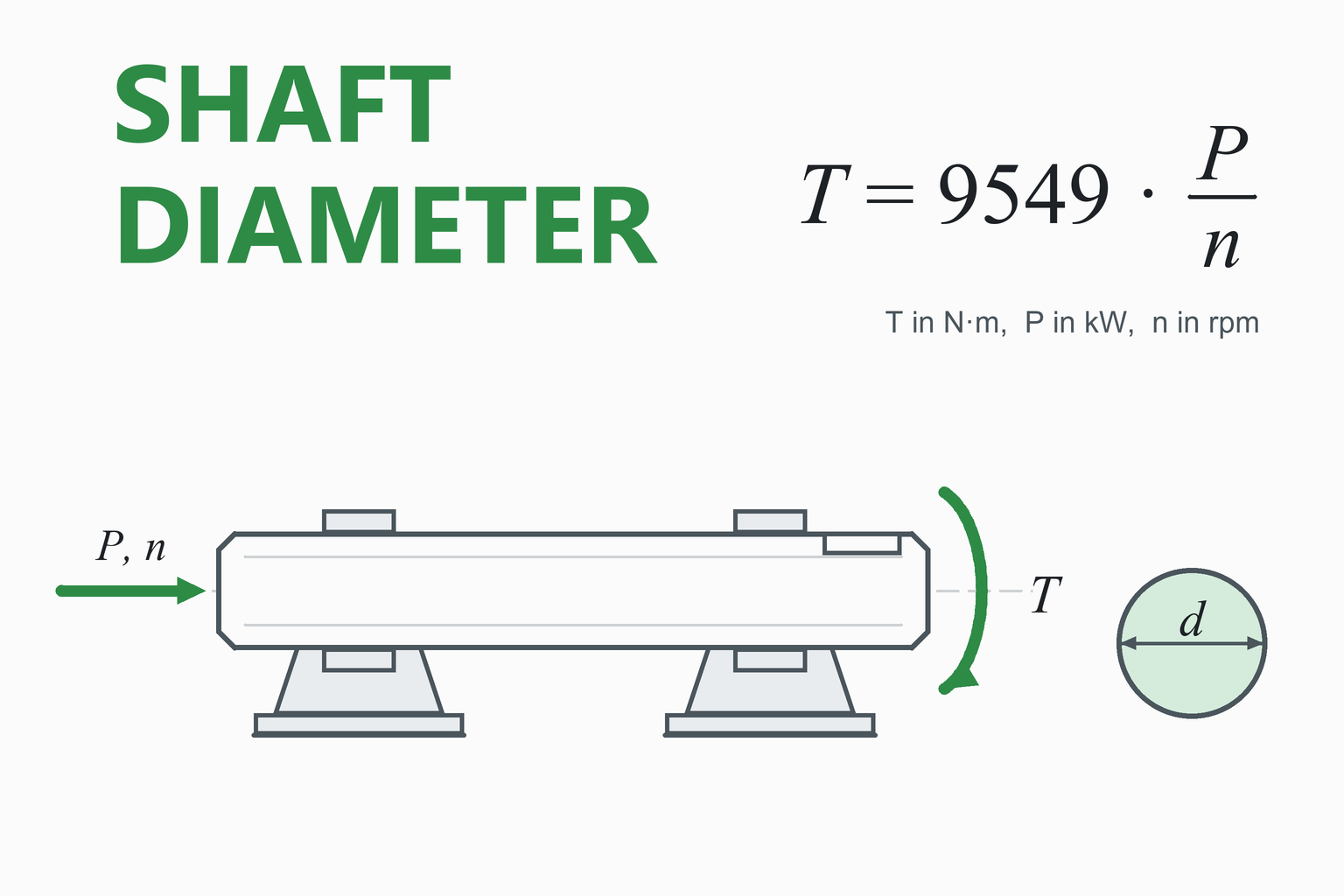
A shaft that transmits power must be thick enough to carry the torque, and torque is set by power and speed: T = 9549 × P(kW) ÷ n(rpm) in N·m. This calculator turns your motor power and shaft speed into torque, adds an optional bending moment, and returns the minimum diameter for a solid or hollow round steel shaft, the next standard size up, the stress and the twist at that size. It works in SI and US units.
Shaft Diameter Calculator
Round solid or hollow shaft · torque with optional bending · steady rotation
| Torque T | — |
|---|---|
| Allowable shear stress | — |
| Equivalent torque Te | — |
| Minimum outer diameter (calculated) | — |
| Standard outer diameter | — |
| Bore diameter at this size | — |
| Margin: required ÷ provided strengthBelow 100% means the standard size is stronger than needed | — |
| Shear stress from torque alone, at this size | — |
| Angle of twist over the length given | — |
| Material used vs a solid shaft of equal strength | — |
Required diameter vs shaft speed at your power
—
Educational and preliminary-design tool. It sizes a round shaft for torque and one bending moment. It does not check fatigue life, stress concentrations at shoulders and keyways, lateral deflection, critical speed, bearings or fits.
Treat the result as a starting size. For a final design, follow your company standard or a full shaft analysis such as the one in Shigley’s Mechanical Engineering Design, and have it checked by a qualified engineer.
How to Use the Calculator
- Enter the load. Give the power and the speed of this shaft, or enter the torque directly if you already know it. In a gearbox every shaft has its own speed and torque.
- Add a bending moment if there is one. A shaft carrying a gear, pulley or sprocket is bent as well as twisted. Enter the largest bending moment on the shaft. If you leave it at 0, the shaft is sized for torque only, which is the minimum.
- Choose the material. The strength and stiffness values fill in automatically and you can overwrite them. Typical values depend on heat treatment and size, so use the data for your actual bar.
- Choose the method. The ASME code method is the best default for a rotating transmission shaft because it builds shock and fatigue allowances into the stress limit. The two static methods are included for teaching and for slowly rotating or stationary shafts.
- Read the standard size and the checks. Look at the margin, the stress and the twist at the standard size. If the twist is large for your length, increase the diameter even though the strength is sufficient.
Tip: Changing a unit drop-down converts the number in that field, so the physical value stays the same. The “SI / US customary” switch changes all units at once.
Worked Example: A 7.5 kW Motor Shaft
Problem. A 7.5 kW electric motor turns a shaft at 1440 rpm. The shaft carries a pulley, which creates a maximum bending moment of 30 N·m. The load is steady, the shaft has a keyway, and the material is AISI 1045 cold-drawn steel (Sy = 530 MPa, Su = 630 MPa). Find the shaft diameter by the ASME code method.
- Torque.
T = 9549.3 × P / n = 9549.3 × 7.5 / 1440 = 49.74 N·m
- Allowable shear stress. The code takes the smaller of 30% of the yield strength and 18% of the tensile strength, then cuts it by 25% for the keyway.
τd = min(0.30 × 530, 0.18 × 630) = min(159, 113.4) = 113.4 MPawith keyway: 0.75 × 113.4 = 85.05 MPa
- Shock and fatigue factors. Rotating shaft, steady load: Km = 1.5 and Kt = 1.0.
- Equivalent torque.
Te = √[(Km·M)² + (Kt·T)²] = √[(1.5 × 30)² + (1.0 × 49.74)²] = 67.07 N·m
- Diameter.
d³ = 16 Te / (π τd) = 16 × 67.07 / (π × 85.05×10⁶) = 4.016×10⁻⁶ m³d = 15.90 mm
- Standard size. The next standard size up is 16 mm. The shear stress from torque alone at 16 mm is 16T/(πd³) = 61.8 MPa, and the strength margin is 98%.
- Twist check. For a 16 mm solid steel shaft (G = 79.3 GPa) the twist is T / (G·J) = 5.59° per metre. A 0.3 m long shaft would twist about 1.7°.
Result: use a 16 mm shaft. The calculated minimum is 15.90 mm, so the standard size is only just large enough: keep it if the length is short, and go up a size if you want margin or less twist.
The same shaft by different methods
The answer depends on the method, so it is worth seeing them side by side for the example above.
| Method | Minimum diameter | What it includes |
|---|---|---|
| ASME code, keyway, torque only (M = 0, Kt = 1) | 14.39 mm | Keyway reduction, allowable stress based on Sy and Su |
| ASME code, keyway, with bending (this example) | 15.90 mm | As above, plus shock and fatigue factor on the bending moment |
| Maximum shear (Tresca), N = 2 | 13.07 mm | Static yield only |
| Distortion energy (von Mises), N = 2 | 12.64 mm | Static yield only |
Why do the static methods give smaller shafts? They only prevent the steel from yielding once. A rotating shaft carrying a bending load sees the bending stress reverse direction on every revolution, and fatigue, not yielding, is what usually breaks it. The ASME method’s low allowable stress (30% of Sy or 18% of Su) and its K factors stand in for that. Do not pick the smaller number just because it is smaller.
Hollow shaft version
With a bore ratio k = 0.6, the same strength needs an outer diameter of 16.65 mm and a bore of 9.99 mm. The cross-section area is about 70% of the solid shaft’s, so the shaft is about 30% lighter for the same torque and bending capacity.
Power, Speed and Torque
Power is the rate of doing work. For a rotating shaft, power equals torque multiplied by angular speed, so torque follows directly from power and speed:
Torque from power and speed
With P in watts, n in rpm and T in N·m. This is the same as T = 9549.3 × P(kW) / n N·m, or T = 63,025 × P(hp) / n lbf·in in US units.
Because torque is inversely proportional to speed, a slow shaft carries much more torque than a fast one at the same power. That is why the low-speed output shaft of a gearbox is always thicker than the input shaft. If friction losses are small, a gear pair with ratio i multiplies the torque by i and divides the speed by i.
Which “horsepower”? The US mechanical horsepower is 745.7 W. The metric horsepower (PS, CV) is 735.5 W, about 1.4% smaller. This calculator uses the mechanical horsepower of 745.7 W.
Stress in a Round Shaft
Twisting a shaft puts it in shear. The shear stress is zero on the centreline and largest at the surface, where the material is farthest from the axis:
Torsional shear stress, solid shaft
Bending stress, solid shaft
Both stresses fall with the cube of the diameter, so a small increase in diameter gives a big gain in strength: 10% more diameter gives about 33% more torque capacity.
On a rotating shaft, a point on the surface sees the bending stress go from tension to compression and back on every turn, while the torsional shear stays roughly constant. That reversing bending stress is why rotating shafts fail by fatigue and why simple static formulas are not enough.
| Symbol | Meaning | SI unit |
|---|---|---|
| P | Power transmitted | W (or kW) |
| n | Shaft speed | rpm |
| T | Torque | N·m |
| M | Bending moment at the critical section | N·m |
| d, do, di | Solid diameter; outer and inner diameter of a hollow shaft | m (or mm) |
| k | Bore ratio di/do | – |
| τd | Allowable shear stress | Pa (or MPa) |
| Sy, Su | Yield and ultimate tensile strength | Pa (or MPa) |
| Km, Kt | Combined shock and fatigue factors for bending and torsion | – |
| N | Factor of safety (static methods) | – |
| G | Shear modulus | Pa (or GPa) |
Method 1: The ASME Code Method
The ASME design code for transmission shafting (ASME B106.1M, now withdrawn but still taught in most machine design courses) sizes a shaft in one step. It sets a low allowable shear stress and multiplies the loads by factors for shock and fatigue:
Allowable shear stress
Shaft diameter
For a solid shaft k = 0. The square-root term is the equivalent torque Te.
| Load condition | Km range | Kt range | Used here |
|---|---|---|---|
| Gradually applied or steady | 1.5 | 1.0 | Km = 1.5, Kt = 1.0 |
| Suddenly applied, minor shock | 1.5 – 2.0 | 1.5 – 2.0 | Km = 2.0, Kt = 2.0 |
| Suddenly applied, heavy shock | 2.0 – 3.0 | 1.5 – 3.0 | Km = 3.0, Kt = 3.0 |
The 0.30 Sy / 0.18 Su limit builds in a large implicit safety factor for fatigue, stress concentrations and uncertainty. That is why the ASME method gives thicker shafts than a static yield check.
Methods 2 and 3: Static Yield Criteria
A yield-based design asks one question: for a chosen factor of safety N, will the steel stay below yield? For a combined bending moment and torque in a solid shaft, the two common criteria give these diameters:
Maximum shear stress (Tresca)
Distortion energy (von Mises)
With M = 0, Tresca gives τmax = Sy/(2N) and von Mises gives τmax = 0.577 Sy/N, the familiar shear-yield estimates.
Von Mises predicts yielding of ductile metals more accurately; Tresca is slightly more conservative. Both ignore fatigue and the stress concentration of the keyway, so they are appropriate for slowly turning or stationary shafts, for a quick static check, or as a first step before a fatigue analysis.
Hollow Shafts
The stress in a shaft is carried mostly by the material near the surface, so removing the core costs little strength and saves a lot of weight. For a hollow shaft with bore ratio k, the diameter formulas above are divided by (1 − k⁴).
- At the same outer diameter, a hollow shaft with k = 0.5 has 6.25% less torque capacity (1 − 0.5⁴ = 0.9375) but 25% less material (1 − 0.5² = 0.75).
- At the same strength, the hollow shaft needs a larger outer diameter but uses less material overall. The result table shows the percentage.
- Very thin walls (k above about 0.8) can buckle or dent and are hard to machine, so the calculator warns above that.
Keyways, Twist and What Is Not Checked
Keyways
A keyway removes material and concentrates stress at its corners. The ASME method accounts for this crudely by cutting the allowable stress by 25%. A real design should check the key itself (shear and bearing) and the keyway’s stress concentration factor.
Angle of twist
A shaft that is strong enough can still twist too much, especially if it is long. The twist over a length L is:
θ is in radians (multiply by 180/π for degrees). Twist falls with the fourth power of the diameter, so a modest size increase cuts it sharply. In the worked example, 16 mm gives 5.59° per metre, while 20 mm would give 2.29° per metre.
Acceptable twist depends on the application. Precision, servo and indexing drives need very little; a simple power drive can tolerate more.
What this calculator does not check
- Fatigue life with stress concentrations at shoulders, grooves and keyways, using a Goodman or similar diagram.
- Lateral deflection and slope at gears and bearings.
- Critical speed, the speed at which the shaft’s bending vibration is excited.
- Key, spline, bearing and fit design.
- Axial loads and thermal effects.
Material Properties Used
| Material | Sy (MPa) | Su (MPa) | G (GPa) | τd, no keyway (MPa) | τd, with keyway (MPa) |
|---|---|---|---|---|---|
| AISI 1018 steel, cold-drawn | 370 | 440 | 79.3 | 79.2 | 59.4 |
| AISI 1035 steel, cold-drawn | 460 | 550 | 79.3 | 99.0 | 74.2 |
| AISI 1045 steel, cold-drawn | 530 | 630 | 79.3 | 113.4 | 85.0 |
| AISI 1045 steel, hot-rolled | 310 | 570 | 79.3 | 93.0 | 69.8 |
| Stainless 304, annealed (ASTM minimum) | 205 | 515 | 77 | 61.5 | 46.1 |
Standard Shaft Sizes
The calculator rounds the calculated minimum up to the next size on these lists. They are common stock and preferred sizes, not an exhaustive standard, so check what your supplier actually holds.
| System | Sizes used |
|---|---|
| Metric (mm) | 6, 8, 10, 12, 14, 16, 18, 20, 22, 24, 25, 28, 30, 32, 35, 38, 40, 42, 45, 48, 50, 55, 60, 65, 70, 75, 80, 85, 90, 95, 100, 110, 120, 130, 140, 150, 160 |
| Inch | 1/2, 5/8, 3/4, 7/8, 1, 1-1/8, 1-1/4, 1-3/8, 1-1/2, 1-5/8, 1-3/4, 1-7/8, 2, 2-1/4, 2-1/2, 2-3/4, 3, 3-1/2, 4, 4-1/2, 5, 5-1/2, 6 (inches) |
Common Mistakes
Using the motor speed for every shaft
After a gearbox, speed falls and torque rises by the gear ratio. Size each shaft with its own speed and torque.
Forgetting bending
Any shaft carrying a gear, pulley or sprocket is bent as well as twisted. A torque-only diameter is a lower bound, not a design.
Using input power instead of output power
Size the shaft for the power it actually transmits, which is the output of the motor or the gear stage, after losses.
Mixing units
N·mm and N·m differ by a factor of 1000, and a cube root hides the error until the shaft is the wrong size. Use the unit drop-downs.
Trusting a static check on a rotating shaft
Yield-based methods ignore fatigue and give smaller shafts. For rotating shafts with bending, use the ASME method or a fatigue analysis.
Ignoring twist
A long or precision shaft can pass the strength check and still twist too much. Check the angle of twist for your length.
Assumptions and Limitations
- Round, solid or concentric hollow cross-section with a constant diameter along the critical section.
- One critical section. You supply the largest bending moment; the calculator does not compute reactions or the moment diagram.
- Steady power, rotating shaft. Shock is covered only through the ASME K factors.
- Ductile steel. The ASME and yield methods are for ductile materials. Brittle materials such as cast iron need other criteria.
- No stress concentrations except the crude 25% keyway allowance in the ASME method.
- The ASME method is a code-style rule of thumb. It is conservative for many cases but is not a substitute for a fatigue analysis in a critical application.
- Preset material values are typical. Always use the certified properties of your material.
How This Calculator Was Verified
The calculation code was tested against results that can be checked independently:
| Check | Expected | Calculator |
|---|---|---|
| Torque, 7.5 kW at 1440 rpm | 9549.3 × 7.5 / 1440 = 49.74 N·m | … |
| US torque, 10 hp at 1750 rpm | 63,025 × 10 / 1750 = 360.1 lbf·in | … |
| Torsion only, no keyway, ASME (M = 0, Kt = 1) | d = (16 T / π τd)1/3, independent calculation | … |
| Worked example, ASME with bending and keyway | d = 15.90 mm, standard 16 mm | … |
| Tresca and von Mises, N = 2, same loads | 13.07 mm and 12.64 mm | … |
| Hollow shaft, k = 0.6, same strength | outer diameter 16.65 mm, area 70.2% of solid | … |
| Twist, 16 mm solid steel shaft, 49.74 N·m, 1 m | 5.59° per metre | … |
The expected values were produced by a separate Python script that does not share code with the page. The “Calculator” column is computed live, by the same code that runs the calculator, in your browser.
Frequently Asked Questions
How do I calculate shaft diameter from power and rpm?
Convert power and speed to torque with T = 9549.3 × P(kW) ÷ n(rpm), in N·m. Then choose an allowable shear stress and solve d = (16T / πτ)1/3 for a solid shaft carrying torque only.
If the shaft is also bent, include the bending moment as in the ASME or von Mises formulas on this page, then round up to a standard size.
Why does a faster shaft need a smaller diameter?
At constant power, torque is inversely proportional to speed. Doubling the speed halves the torque, and because diameter varies with the cube root of torque, the required diameter falls by about 21% (a factor of 0.794). The chart under the calculator shows this.
What allowable shear stress should I use?
For a transmission shaft, the ASME code rule is the smaller of 30% of the yield strength and 18% of the tensile strength, reduced by 25% if there is a keyway. For a static yield check, use the shear-yield estimate 0.577 Sy/N (von Mises) or 0.5 Sy/N (Tresca) with a factor of safety N.
Your company standard or customer specification may require something different.
What is the difference between the ASME, Tresca and von Mises methods?
The ASME method is a code-style rule with a low allowable stress and shock and fatigue factors, which is why it is the traditional choice for rotating transmission shafts. Tresca and von Mises are static yield criteria: they only stop the steel yielding once, at the factor of safety you choose.
Von Mises is closer to the real behaviour of ductile steel, and Tresca is slightly more conservative. Neither covers fatigue, so they give smaller shafts than the ASME method.
Does a keyway weaken the shaft?
Yes. A keyway removes material and concentrates stress at its corners. The ASME method cuts the allowable stress by 25% as a simple allowance. For a final design, check the keyway’s stress concentration factor in a fatigue analysis and check the key’s own shear and bearing stress.
How much material does a hollow shaft save?
For the same strength, a hollow shaft with a bore ratio of 0.6 needs about 30% less material than a solid shaft (see the worked example). At the same outer diameter, a bore ratio of 0.5 removes 25% of the material but only 6.25% of the torque capacity.
Which speed and power do I use with a gearbox?
Use the speed and torque of the shaft you are sizing. For an ideal gear pair, torque on the output shaft equals the input torque multiplied by the gear ratio, and the speed is divided by the ratio. Friction losses reduce the output power slightly.
Does this calculator check fatigue, critical speed or deflection?
No. It sizes a round shaft for torque and one bending moment, and reports the twist. A complete shaft design also checks fatigue life with stress concentrations at shoulders and keyways, lateral deflection and slope, critical speed, and the keys, splines, bearings and fits.
Is a bigger shaft always safer?
It is stronger, but not automatically better. A larger shaft is heavier and costlier, and may not fit the bearings, couplings and gears you have chosen. Pick the smallest standard size that meets the strength, twist and deflection limits with an appropriate margin.
References and Further Reading
- Budynas, R. G., & Nisbett, J. K. Shigley’s Mechanical Engineering Design. McGraw-Hill. (Shafts and shaft components; material property tables.)
- Mott, R. L., Vavrek, E. M., & Wang, J. Machine Elements in Mechanical Design. Pearson. (Shaft design and the ASME-style approach.)
- Norton, R. L. Machine Design: An Integrated Approach. Pearson.
- Bhandari, V. B. Design of Machine Elements. McGraw-Hill Education India. (ASME code equation for shafts and the Km, Kt table.)
- Khurmi, R. S., & Gupta, J. K. A Textbook of Machine Design. S. Chand.
- ASME B106.1M-1985, Design of Transmission Shafting (withdrawn; the method remains widely taught).